
My experience of AutoCAD 2011 (aka Hammer).
AutoCAD 2011 ('twenty eleven') was released on Thursday, 25 March 2010.
This is the 25th version of AutoCAD.
Previous AutoCAD version AutoCAD 2010 and newer version AutoCAD 2012.
New and/or enhanced functions
New and/or enhanced functions and some bug fixes.
No New file format "AutoCAD 2010 Drawing" is used. The version number is 18.1.
The big news in AutoCAD 2011 are
- Surface Modeling - NURBS surfaces
- Point Cloud Files - up to 2 billion points (2,000,000,000)
- Materials Browser
- Parametric Drawing - Infer Constraints
- Object Transparency
- Polylines - multi-functional grips
User Interface
A dark gray background in modelspace is now default.
The traditional dot grid has been replaced with horizontal and vertical gridlines.
Quick Access toolbar displays the name of the current workspace. As default Quick Access toolbar now includes both the Save and the Save As tools.
![]()
![]() New Navigation bar that replaces the navigation tools that were previously accessible on the Status bar. Integrated support for 3D Connexion devices. Model space variant to the left and paper space variant to the right. You can select where it is docked and if it should be linked to the ViewCube.
New Navigation bar that replaces the navigation tools that were previously accessible on the Status bar. Integrated support for 3D Connexion devices. Model space variant to the left and paper space variant to the right. You can select where it is docked and if it should be linked to the ViewCube.
ViewCube has been enhanced to support the 2D wireframe visual style.
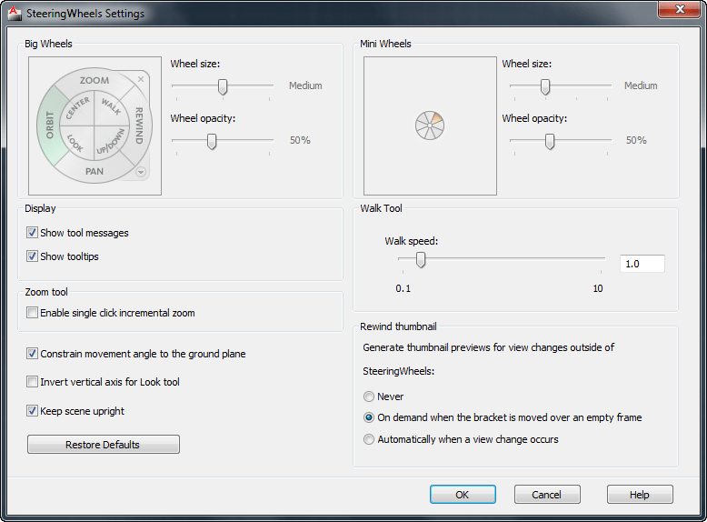
SteeringWheel Settings dialog box updated.
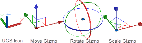
The UCS icon has been updated to display a different color for each axis: X for red, Y for green, and Z for blue. In addition, the appearance of 3D gizmos has been updated for clarity and consistency.
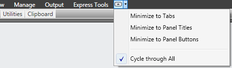
Ribbon cycle options.
The Insert tab includes a Point Cloud panel and Content panel with access to Design Center and Autodesk Seek web service. Autodesk Seek has been removed from the Output tab.
The View tab has been updated to include the Visual Styles panel. The Windows panel includes new User Interface and Toolbar controls that enable you to toggle the display of various user interface elements, including Autodesk ViewCube and ShowMotion navigation widgets, the Navigation bar, and the Text window. The Status bar controls, which have been removed from the Windows panel, are now only on the Status bar.
Customize User Interface dialog box now supports Fold panels.
Visible news
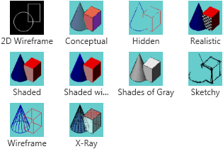
Five new predefined visual styles including: Shaded, Shaded with Edges, Shades
of Gray, Sketchy, and X?Ray.
Object Visibility enable you to control object visibility independent from layer
visibility. 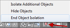 The Object Visibility tools are accessible from the right?click menu when objects are selected as well as when no objects are selected. When you use the Isolate Objects tool, only the selected objects remain visible in the drawing. All other objects are hidden. The OBJECTISOLATIONMODE system variable controls whether isolated/hidden objects persist between drawing sessions. Default setting is temporary for current drawing session with value 0. To persist use value 1. A lightbulb icon on the status bar indicates whether object isolation is active in the drawing.
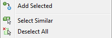
Select Similar tool enables you to select an object and automatically include all other objects of the same type and with the same properties, in a new selection set. You can access it from the right?click menu when objects are selected.
Add Selected tool enables you to quickly create a new object in your drawing based on the properties of an existing object. For example, if you use the Add Selected tool and select a polyline, AutoCAD automatically launches the PLINE command with basic object properties including color, layer, linetype, linetype scale, plotstyle, lineweight, transparency, and material preset to match the selected object.
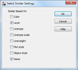
A Settings option (accessible when you enter SELECTSIMILAR at the command line) enables you to specify which properties to filter. If only the Layer property is enabled when you select a circle, for example, AutoCAD automatically selects all circles on the same layer as the one you selected. If both the Layer and Linetype properties are enabled, however, AutoCAD selects only the circles on the same layer and with the same linetype as the selected one.
The Select Similar tool also enables you to select more than one object and create the matching selection set accordingly. For example, if the Layer filter is enabled and you select two circles, each on different layers, AutoCAD selects all the circles on both layers. If, instead, you select a circle and a line, AutoCAD selects all the circles on the same layer as the selected circle and all the lines on the same layer as the selected line. In addition to general object properties, you can filter selections based on objectspecific properties, including object style and reference name. Object Style properties apply to text and mtext, leaders and mleaders, dimensions and tolerances, and tables and multilines. Reference names apply to blocks and externally referenced files, including xrefs and images as well as PDF, DWG™, or DGN files.
In addition to the new Select Similar tool, a new option has been added to the PICKADD system variable. When PICKADD is set to a value of 2 (as it is now by default), objects that you select using the SELECT command remain selected in a “pick first” state even after you end the SELECT command.
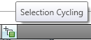 Easily select overlapping objects using the new selection cycling functionality. You can enable selection cycling from a control on the Status bar (right click to access the Selection Cycling options). When you try to select an object that overlaps other objects, AutoCAD displays a list of all the overlapping objects. As you pass the cursor over an object in the list, the relevant object in the drawing highlights, click on any object in the list and it gets selected. You can also click on the same location multiple times and the objects with be selected one at a time. To filter the type of subobjects displayed (vertices, edges, or faces) use the SUBOBJSELECTIONMODE system variable. You can also set this option with the SELECTIONCYCLING system variable.
The Action Recorder enables you to delete or insert user messages for View Change operations. The macro list displays the most recently used macros above the separation bar and all available macros below it.
Parametric Constraints
The 2D parametric functionality has been enhanced, and includes predefined command macros to access options within in the GEOMCONSTRAINT and DIMCONSTRAINT commands.
For example, instead of launching the GEOMCONSTRAINT command and then selecting the Perpendicular option, you can launch the GCPERPENDICULAR command directly. Repeating the last command automatically repeats the last command as well as the specific option.
Object highlighting when you roll over an icon on a constraint bar or when you select a parameter in the Parameters manager supports the Visual Effects settings you specify on the Selection tab of the Options dialog box (dashed and thickened by default). Additional improvements to geometric and dimensional constraint functionality enable you to create and edit parametrically constrained geometry faster than ever before.
Geometric Constraints
AutoCAD 2011 significantly simplifies the process of adding geometric constraints to 2D AutoCAD geometry. AutoCAD can infer geometric constraints as you create and modify geometry. A new Infer Constraint button on the status bar enables you to toggle inferred constraints on and off similar to toggling object snaps on and off. This toggle is also available on the Geometric tab of the Constraint Settings dialog box.
 Using inferred constraints automatically applies coincident constraints for Endpoint, Midpoint, Center, Node, and Insertion objects snaps. For example, if you draw a circle by snapping its center to the midpoint of a line, AutoCAD automatically applies a coincident constraint between the center of the circle and the midpoint of the line. If you move the circle, the line goes with it. The same powerful functionality applies to editing commands. If, for example, you copy the insertion of a block to the endpoint of a line, AutoCAD automatically applies a coincident constraint between those two points. When you move the line, the block maintains its position at the endpoint of the line.
In addition to creating point?to?point coincident constraints with the previously mentioned object snaps, you can use the Nearest object snap to apply a coincident constraint between a point and an object. For example, if you draw the center of a circle on a line using the Nearest object snap, the center of the circle has the flexibility of moving anywhere along the line including the virtual extension of the line.
The Perpendicular and Tangent object snaps automatically apply perpendicular or tangent constraints between the object being created or edited and the object being snapped to. They also apply a point?topoint or point?to?object coincident constraint if appropriate. Using the Parallel object snap automatically applies a parallel constraint but no coincident constraints are applied since, by definition, the two objects never intersect. When you draw horizontal or vertical lines and polyline segments, inferred horizontal and vertical constraints automatically apply to those segments.
Inferred constraints enhance the behavior of rectangles, fillets, and chamfers by automatically applying appropriate geometric constraints. For example, if you draw a rectangle (using the RECTANG command), AutoCAD automatically applies a pair of parallel constraints and a perpendicular constraint to the closed polyline. When you modify the size and shape of the rectangle, you can rest assured that it will remain a rectangle with parallel sides and perpendicular corners. Creating a fillet automatically applies coincident and tangent constraints between the newly created arc and the existing pair of lines helping maintain the fillet even when the arc or lines are modified. Similarly, creating a chamfer applies coincident constraints between the newly created line and the existing pair of lines.
Even after you’ve applied constraints, you can temporarily relax them by pressing the CTRL key while editing constrained objects.
Improved support of geometric constraints for ellipses and text. You can now apply Parallel, Perpendicular, Collinear, Horizontal, and Vertical constraints between the major or minor axes of an ellipse and other objects.
 Similarly, you can apply Parallel, Perpendicular, Collinear, Horizontal, and Vertical constraints to the rotation angle of text objects. In addition, text and mtext objects behave consistently and predictably, with the identified insertion point of the object being the constrainable point.
One problem found is that to select the text it is needed to click a bit below the text.
The AutoConstrain functionality in AutoCAD 2011 has been updated to include the Equal constraint. When you use AutoConstrain with the Equal option enabled, the Equal constraint is automatically applied to lines and polyline segments of equal length and arcs and/or circles of equal radius.
Constraint bars are enhanced to provide more control and flexibility. You can select multiple objects for showing or hiding constraint bars using standard selection methods, including Window, Crossing, Fence, and Implied Window/Crossing. Quickly display all constraint bars in their original position using the new Reset option. And, a new setting in the Geometric tab of the Constraint Settings dialogs enables you to show constraint bars when objects are selected even if those constraint bars are currently hidden. When the geometry is no longer selected, the temporarily displayed constraint bars are, once again, hidden. When you move a constraint bar and then edit the related geometry, the constraint bar maintains its position relative to the geometry.
![]() The new constraint icons for Fix, Horizontal, and Vertical constraints visually indicate whether they apply to an object or to a point. The symmetric constraint icon is also updated to indicate whether it is identifying a symmetrical point or object, or the symmetric line.
The new constraint icons for Fix, Horizontal, and Vertical constraints visually indicate whether they apply to an object or to a point. The symmetric constraint icon is also updated to indicate whether it is identifying a symmetrical point or object, or the symmetric line.
The DIMCONSTRAINT command includes a new Convert option to convert associative dimensions to dimensional constraints rather than it being the default behavior.
When entering dimensional constraint values in?place, you can click on an existing dimensional constraint to insert the constraint name. When dynamic dimensional constraints reference another parameter, the parameter text is prepended with “fx:” to help prevent you from accidentally assigning a constant value to a parameter that references other variables.
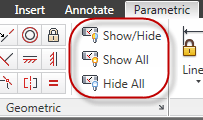 New tools on the Dimensional Panel of the Parametric tab provide you with more control over the display of dimensional constraints. Using the Show/Hide tool you can select the specific dimensional constraints you want to show or hide.
The Parameters Manager offers significant improvements. It includes a new Filters pane where you can define parameter groups that display a subset of the parameters. Create new filter groups using the button at the top of the Parameters Manager or by selecting the option from the rightclick menu. With your filter groups created, you can then drag parameters into them. The right?click menu for parameters in the Parameters Manager is updated with additional options including the ability to display the Filter tree and to remove parameters from a group.
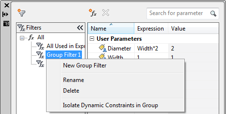
A new search box filters the parameters displayed in the grid control based on the parameter name. Column tooltips display the full name of the column as well as a description.
Additional enhancements to the Parameters Manager simplify the terminology for dimensional constraints and user variables created in the drawing editor versus the block editor. The Show column in the Block Editor includes a new option to convert between dimensional constraint parameters or user parameters defined in the drawing editor versus the block editor. In the Block Editor, icons are displayed for action parameters, attributes, and user parameters.
Transparency
AutoCAD 2011 includes a new transparency property that enables you to apply transparency to objects and layers in the same way you apply colors, linetypes, and lineweights.
You can set transparency by layer, by block, or individually for an object. The default transparency value for layers and objects is 0, and you can set it as high as 90.
![]()
The Layer Properties Manager (palette and dialog), the Layer States Manager, the Layer Filter dialog, and the Layer Translator have all been updated to reflect the new transparency property. In the Layer Properties Manager, a new column for Transparency is available in modelspace and layouts, and a column for Viewport (VP) Transparency is available in layouts and floating modelspace viewports.
You can set transparency for individual objects just like color and linetype. Setting a transparency value for an individual object overrides the layer transparency setting for that object. You can access object transparency from a number of places: the Properties palette, Quick Properties, or the ribbon. The new CETRANSPARENCY system variable sets the transparency property for new objects.
The SetByLayer Settings dialog has been updated to include Transparency as one of the available properties.
Transparency has also been added to the Quick Select, Filter, and Match Property Settings dialogs as well as the CHPROP, CHANGE, ?LAYER, VPLAYER, and LIST commands.
A button has been added to the status bar to enable you to temporarily turn off transparency display (TRANSPARENCYDISPLAY system variable), similar to the behavior of the lineweight display button. This does not affect plotting. However, you have the option to turn off transparency when plotting. The Plot and Page Setup dialogs both include a checkbox for transparency (PLOTTRANSPARENCY), similar to the behavior for plot styles. When this option is enabled, AutoCAD rasterizes the entire drawing for plotting, slowing down the plotting process.
Prior to AutoCAD 2011, images had a setting, also called “transparency,” that controlled whether the background of a bitonal image was clear or opaque. This property has been renamed to “background transparency” to distinguish it from the new “transparency” property. You can apply both background and object transparencies to images in AutoCAD 2011.
Linetype
You can control the orientation of text in linetypes with the alignment code "U". GAS and HOT_WATER_SUPPLY already has this in the new .LIN files.
Windows 7
Jump List support.
ActiveX API
ActiveX API
The following outlines the additions and changes made to the ActiveX API in AutoCAD 2011 and AutoCAD 2011-based products.
Enums
AcEntityName (Changed)
        acNurbSurface = 51 (New)
AcSaveAsType (Changed)
        ac2010_dwg = 48 (New)
        ac2010_dxf = 49 (New)
        ac2010_Template = 50 (New)
        acNative = 48 (Changed)
AcWireframeType (New)
        acIsolines = 0
        acIsoparms = 1
AcSplineKnotParameterizationType (New)
        acChord = 0
        acSqrtChord = 1
        acUniformParam = 2
        acCustomParameterization = 15
AcSplineFrameType (New)
        acShow = 0
        acHide = 1
AcSplineMethodType (New)
        acFit = 0
        acControlVertices = 1
AcPointCloudColorType (New)
        acByColor = 0
        acPreset = 1Classes
IAcadEntity2 (New)
        EntityTransparency - Property
IAcadRasterImage2 (New)
        EntityTransparency - Property
IAcad3DFace2 (New)
        EntityTransparency - Property
IAcad3DPolyline2 (New)
        EntityTransparency - Property
IAcadRegion2 (New)
        EntityTransparency - Property
IAcad3DSolid2 (New)
        EntityTransparency - Property
IAcadArc2 (New)
        EntityTransparency - Property
IAcadAttribute2 (New)
        EntityTransparency - Property
IAcadBlockReference2 (New)
        EntityTransparency - Property
IAcadCircle2 (New)
        EntityTransparency - Property
IAcadEllipse2 (New)
        EntityTransparency - Property
IAcadHatch2 (New)
        BackgroundColor - Property
        EntityTransparency - Property
IAcadLeader2 (New)
        EntityTransparency - Property
IAcadMLeader2 (New)
        EntityTransparency - Property
IAcadLWPolyline2 (New)
        EntityTransparency - Property
IAcadLine2 (New)
        EntityTransparency - Property
IAcadMText2 (New)
        EntityTransparency - Property
IAcadPoint2 (New)
        EntityTransparency - Property
IAcadPolyline2 (New)
        EntityTransparency - Property
IAcadPolygonMesh2 (New)
        EntityTransparency - Property
IAcadRay2 (New)
        EntityTransparency - Property
IAcadShape2 (New)
        EntityTransparency - Property
IAcadSolid2 (New)
        EntityTransparency - Property
IAcadSpline2 (New)
        KnotParameterization - Property
        SplineFrame - Property
        SplineMethod - Property
        Degree2 - Property
        Closed2 - Property
        EntityTransparency - Property
IAcadText2 (New)
        EntityTransparency - Property
IAcadTolerance2 (New)
        EntityTransparency - Property
IAcadTrace2 (New)
        EntityTransparency - Property
IAcadXline2 (New)
        EntityTransparency - Property
IAcadPViewport2 (New)
        EntityTransparency - Property
IAcadPolyfaceMesh2 (New)
        EntityTransparency - Property
IAcadMLine2 (New)
        EntityTransparency - Property
IAcadExternalReference2 (New)
        EntityTransparency - Property
IAcadTable2 (New)
        EntityTransparency - Property
IAcadOle2 (New)
        EntityTransparency - Property
IAcadHelix2 (New)
        EntityTransparency - Property
IAcadSurface2 (New)
        WireframeType - Property
        MaintainAssociativity - Property
        ShowAssociativity - Property
        EdgeExtensionDistances - Property
        EntityTransparency - Property
IAcadPlaneSurface2 (New)
        WireframeType - Property
        MaintainAssociativity - Property
        ShowAssociativity - Property
        EdgeExtensionDistances - Property
        EntityTransparency - Property
IAcadExtrudedSurface2 (New)
        WireframeType - Property
        MaintainAssociativity - Property
        ShowAssociativity - Property
        EdgeExtensionDistances - Property
        EntityTransparency - Property
IAcadRevolvedSurface2 (New)
        WireframeType - Property
        MaintainAssociativity - Property
        ShowAssociativity - Property
        EdgeExtensionDistances - Property
        EntityTransparency - Property
IAcadSweptSurface2 (New)
        WireframeType - Property
        MaintainAssociativity - Property
        ShowAssociativity - Property
        EdgeExtensionDistances - Property
        EntityTransparency - Property
IAcadLoftedSurface2 (New)
        StartSmoothMagnitude - Property
        EndSmoothMagnitude - Property
        StartSmoothContinuity - Property
        EndSmoothContinuity - Property
        Periodic - Property
        WireframeType - Property
        MaintainAssociativity - Property
        ShowAssociativity - Property
        EdgeExtensionDistances - Property
        EntityTransparency - Property
IAcadWipeout2 (New)
        EntityTransparency - Property
IAcadSubDMesh2 (New)
        EntityTransparency - Property
IAcadNurbSurface (New)
        CvHullDisplay - Property
        WireframeType - Property
        MaintainAssociativity - Property
        ShowAssociativity - Property
        EdgeExtensionDistances - Property
        EntityTransparency - Property
IAcadDimAligned2 (New)
        EntityTransparency - Property
IAcadDimAngular2 (New)
        EntityTransparency - Property
IAcadDimDiametric2 (New)
        EntityTransparency - Property
IAcadDimOrdinate2 (New)
        EntityTransparency - Property
IAcadDimRadial2 (New)
        EntityTransparency - Property
IAcadDimRotated2 (New)
        EntityTransparency - Property
IAcadDim3PointAngular2 (New)
        EntityTransparency - Property
IAcadDimArcLength2 (New)
        EntityTransparency - Property
IAcadDimRadialLarge2 (New)
        EntityTransparency - Property
IAcadPointCloud (New)
        InsertionPoint - Property
        scale - Property
        Rotation - Property
        UseEntityColor - Property
        Locked - Property
Still missing
Still missing. Wish list for the next time
See also old wishes found in my pages about AutoCAD 2010 and AutoCAD 2009 and AutoCAD 2008
Selection cycling should benefit from also be able to show layer of objects. Imagine if you have two identical objects and only the layer is different. Another thing that might be helpful is to be able to use the up and down arrows on the keyboard to activate the Selection dialog. Now you have to either stay still and click multiple times or to move the mouse to the Selection dialog box.
If you have something you miss or wish for please contact us and we might add it here.
Existing bugs
Existing bugs, defects, feature limitation or other issues.
Paragraph Spacing is limited to 4 for both before and after.
Removed
Removed
The VBA module is unsupported by Autodesk and will not be available in future releases of AutoCAD. Autodesk announced with the release of AutoCAD 2012 that VBA is still available for a limited time.
Tips & Tricks
Tips & Tricks
Here is the list for the new AUGI AutoCAD Top Ten Wishes for November 2009! Let's see if any of these features make it into AutoCAD 2011.
1. Join Individual Hatch Areas
The ability to join individually created hatch areas into a single hatch object.
2. Toolpalettes in CUI
Add toolpalettes to the CUI so they can be easily imported/transferred.
3. Window and Crossing Selection box Aligned with Crosshairs
When crosshairs are rotated, the window and crossing selection box should align with crosshairs.
4. Graphically create or change hatch patterns
The ability to graphically create or change hatch patterns.
5. Fillet 3D Polylines
The ability to fillet 3D Polylines
6. Control Mirroring of Text in Blocks
Ability to control whether text/attributes are mirrored in blocks when the block is mirrored.
7. Create and Zip Complete Drawing Package
The ability to create and zip a drawing package that includes multiple formats of same drawing (PDF, DWF) using eTransmit
8. Dialog for Complex Linetypes
An editor for creation of complex linetypes.
9. Attributes Always Horizontal
The ability to set an attribute relative to UCS regardless of the rotation of the block.
10. Enable Renaming of Anonymous Blocks
The ability to rename anonymous blocks in the properties dialog or quick properties dialog.
File navigation dialogs freeze in Windows 7
Issue
You are running AutoCAD (or an AutoCAD-based vertical product) in Windows 7 and you have used a command that invokes an AutoCAD file navigation dialog, e.g., Open, Save, ImageAttach, etc. Your system immediately locks up requiring a hard reset of the computer.
Solution
This issue is caused by the default driver that shipped with Windows 7 for the NVIDIA® video card. Updating your Windows 7 system to the latest certified driver resolves this problem. Refer to the Graphics Hardware List for a list of certified drivers for your video card:
http://www.autodesk.com/autocad-graphicscard
AutoCAD 2011 also is referred to as ACAD2011 or ACAD 2011.
Solution to the problem: The Ribbon does not have any tabs or panels currently loaded.
Readme
Readme: http://docs.autodesk.com/ACD/2011/ENU/filesReadme
Configuring a Database to Use With AutoCAD Drawings (dbConnect)
AutoCAD 2011 for 64-bit does not support Microsoft Jet 4.0 OLE DB Provider (for .MDB connectivity) and Microsoft OLE DB Provider for ODBC Drivers (for .XLS connectivity). For more information, see Substituting SQL Server for OLE DB in the Driver and Peripheral Guide.
Visual Basic for Applications (VBA)
Microsoft Visual Basic® for Applications (VBA) is available for free download at http://www.autodesk.com/vba-download. Autodesk is transitioning from VBA technology to .NET Framework. The VBA module is available for AutoCAD 2011-based products as an unsupported feature. It will not be available in future releases of AutoCAD. Autodesk will provide documentation and other assistance to help customers and developers migrate from VBA to .NET Framework.
UPDATE: As of January 31, 2014, Autodesk is no longer authorized to distribute VBA 6 or earlier versions of VBA for use with Autodesk AutoCAD and other Autodesk products. This change affects the availability to download and install VBA for Autodesk AutoCAD 2013 or earlier.
API Compatibility
AutoCAD 2011 is binary compatible with AutoCAD 2010, but not AutoCAD 2009. To make applications developed for AutoCAD 2009 or earlier releases compatible with AutoCAD 2011, you must recompile them with current ObjectARX libraries. Applications developed for AutoCAD 2011 with ObjectARX will not work in prior releases.
In AutoCAD 2011, if you enter the VLIDE command, pressing F1 opens the Help Home page. To open the AutoLISP Reference Guide, on the Help Home page, on the left-hand side, select AutoLISP Reference Guide from the table of contents. In Visual LISP™, some commands may not have F1 functionality, however, context-sensitive help is working. To display context-sensitive help, after you enter the command name, press Ctrl + F1.
For help with vla-* functions, see the AutoCAD ActiveX and VBA Reference available at C:\Program Files\Common Files\Autodesk Shared\acadauto.chm (not available online).
Hardware and software requirements
Whether your Windows operating system is the 32-bit or the 64-bit version, the version is automatically detected during installation. The appropriate version of AutoCAD is installed. A 64-bit version of AutoCAD cannot be installed on a 32-bit system and vice-versa.
See the following table for hardware and software requirements.
|
32-bit Hardware and Software Requirements |
||
|---|---|---|
|
Operating systems |
Service Pack 2 (SP2) or later for the following:
Service Pack 1 (SP1) or later for the following:
The following operating systems:
|
|
| Browser | Internet Explorer® 7.0 or later | |
| Processor |
Windows XP - Intel® Pentium® 4 or AMD Athlon™ Dual Core, 1.6 GHz or higher with SSE2 technology Windows Vista or Windows 7 - Intel Pentium 4 or AMD Athlon Dual Core, 3.0 GHz or higher with SSE2 technology |
|
| Memory |
2 GB RAM |
|
| Display resolution | 1024 x 768 with True Color | |
| Hard disk | Installation 1.8 GB | A 32-bit AutoCAD cannot be installed on a 64-bit Windows operating system and vice-versa. |
| Pointing device | MS-Mouse compliant | |
| Additional Requirements for3D Modeling |
|
|
|
64-bit Hardware and Software Requirements |
||
|---|---|---|
|
Operating systems |
Service Pack 2 (SP2) or later for the following:
Service Pack 1 (SP1) or later for the following:
The following operating systems:
|
|
| Browser | Internet Explorer 7.0 or later | |
| CPU type |
AMD Athlon 64 with SSE2 technology AMD Opteron™ with SSE2 technology Intel Xeon® with Intel EM64T support and SSE2 technology Intel Pentium 4 with Intel EM64T support and SSE2 technology |
|
| Memory |
2 GB RAM |
|
| Display resolution | 1024 x 768 with True Color | |
| Hard disk | Installation 2 GB | A 64-bit AutoCAD cannot be installed on a 32-bit Windows operating system and vice-versa. |
| Pointing device | MS-Mouse compliant | |
| 3D Modeling Additional Requirements |
|
|
Note that Adobe Flash Player is not installed by default. If a version of Flash is not currently installed on your system, a message is displayed requesting that you install it. Flash Player can be installed from the product media or Adobe’s website - www.adobe.com.
Installation and setup
To install AutoCAD, you must have administrator permissions. You do not need to have domain administrative permissions. See your system administrator for information about administrative permissions.
You do not need administrator permissions to run AutoCAD. You can run the program as a limited user.
You can migrate your custom settings and files from previous releases of AutoCAD (AutoCAD 2000 through AutoCAD 2011).
Autodesk Design Review 2011 is not installed by default when you install AutoCAD. It is recommended that Design Review be installed if you need to view DWF or DWFx files.
What features get installed during a Typical or Custom installation?
A Typical installation also includes the Express Tools library. The library provides additional productivity tools.
| CAD Standards | Contains tools for reviewing design files for compliance with your standards. |
| Database | Contains database access tools. |
| Dictionaries | Contains multi-language dictionaries. |
| Drawing Encryption | Allows you to use the Security Options dialog box to protect a drawing with a password. |
| Express Tools | Contains AutoCAD support tools and utilities (not supported by Autodesk). |
| Fonts | Contains AutoCAD fonts and TrueType fonts. |
| Autodesk Seek | Autodesk Seek.
NoteSeek will only be installed in the English version of AutoCAD.
|
| Welcome Screen | Contains learning resources to help discover the product. |
| License Transfer Utility | Allows users to transfer an Autodesk product license between computers.
NoteThe utility will not be installed on unlocked versions of AutoCAD.
|
| Migrate Custom Settings | Migrates custom settings and files from previous version of your product to this version. |
| Initial Setup | Allows users to perform some basic customization of AutoCAD (online content, workspaces) based on their units system, industry, and commonly used task-based tools. |
| Reference Manager | Allows users to view and edit the paths of externally referenced files associated with a drawing. |
| Samples | Contains various feature sample files. |
| Tutorials | Contains tutorials. |
Custom Folder in Deployments
In the AutoCAD 2011 Deployment Wizard the Select Installation Folders for Support Content page allows you to specify a custom folder in which to copy support content.
If you specify a folder location that has Read Only permission at the user level according to the Microsoft Vista User Access Control, then AutoCAD may become unstable. To avoid this, ensure that you have Write permission on your Microsoft Vista machine when creating your deployment with the Custom Folder option.
Single Share Folder Option for Deployment Images
When using the Single Shared Folder option to create a deployment image, specify a folder name to avoid creating an invalid deployment image. Do not leave the folder name as “<Shared folder path>”.
Licensing
Running a Network License Manager on Microsoft Windows Vista
When starting the network version of AutoCAD 2011 on a Microsoft Windows Vista workstation, you may encounter licensing error -15 if the Network License Manager is running on Windows Vista (FLEXlm server version 11.4.100).
Do the following:
•Install the latest service pack and updates for Microsoft Windows Vista.
If you continue to encounter errors, do the following:
•On the Start menu (Windows Vista), click Control Panel Network and Sharing Center Manage Network Connections. Right-click Local Area Connection. Click Properties. Clear the check box for Internet Protocol 6 (TCP/IPv6). Click OK.
FLEXIm License is Created in Two Locations
The FLEXlm License Finder dialog box may not display when AutoCAD 2011 is started for non-administrative users who are using Windows Vista 64-bit. The license server path information is stored in the HLKM\SOFTWARE\Wow6432Node path, which is not accessible to non-administrative users.
To fix this problem, replicate the license server path information stored in the above path to go to the HKLM\software\FLEXlm License Manager path.
Feature Limitations and Notes
The following are known issues with this release:
Blocks
In the Block Properties table, you cannot enter a combination of decimals and fractions. All numerical values must be either decimals or fractions.
Dimensional Constraints
Dimensional constraints do not behave as associative dimensions when opened in previous versions of AutoCAD. To reassociate dimensions, use the DIMREASSOCIATE command.
Hatch
By default, a preview of the hatch displays as you move your mouse over bounded areas. To improve the response time in large drawings, turn off the hatch preview feature with the HPQUICKPREVIEW system variable.
Materials
Do NOT change the default location of the installed Materials2011 folder. Changing the default location of this folder may cause unpredictable results.
When you install AutoCAD 2011, by default, the Autodesk Material Library is also installed. In AutoCAD 2011, AutoCAD 2010 drawings may display with lower resolution textures. This is because the Autodesk Material Library 2011 has lower resolution than the Autodesk Material Library 2010. For image fidelity, install the Autodesk Material Library 2011 Medium Image Library. In the AutoCAD 2011 installation wizard, on the Select Products to Install page, select Autodesk Material Library Medium Image Library.
HDR and EXR files are not supported even though the format displays in the Materials Editor. If you use materials in these formats, your drawing will render as all black.
In the Duplicate Appearance Name dialog box, if you select Replace, the material is not replaced in the Materials Library as expected. To workaround, in the Duplicate Appearance Name dialog box, select Keep Both.
If you create a Material library on a network computer, you must restart AutoCAD to make it available on your network. If you do not and attempt to use the file on other network computers, an error displays and you cannot open the file.
Polylines
Autoconstraining a polyline that has many points may significantly reduce AutoCAD performance.
Rotating Constrained Geometry
Rotating horizontally or vertically constrained geometry may give unpredictable results.
Toolclips
On Windows XP (64-bit), toolclips (videos within tooltips) do not display.
Transparency
The transparency property of objects is ignored when exporting to WMF, SAT, STL, EPS, DXX, or DGN formats.
The effect of locked layer fading and other fading effects (xrefs, images, DWF and DGN underlays) is cumulative with object-based transparency. As a result, objects that use both fading and transparency may be difficult to see.
Updates & Service Packs
Updates & Service Packs
- Vault 2012 Client Update for AutoCAD 2011
- AutoCAD 2011 Update 2
- Autodesk IPv4 Network License Manager for Windows
- Certified Hardware XML Database Update
- AutoCAD 2011 Update 1.1
- AutoCAD and AutoCAD LT Layer Manager Hotfix
- Certified Hardware XML Database Update
- SAMReport-lite for Windows 7
- Autodesk InfoCenter Hot Fix
- AutoCAD 2011 CHM-Based Help
- Asian Character Command Line Input Hotfix For AutoCAD 2011
- Liveupdate HotFix for French/Italian/Spanish AutoCAD 2011 64-bit versions
- PublishToWeb HotFix for French/Italian/Spanish AutoCAD 2011 64-bit versions
- Autodesk Materials Library 2011 Update 1
Knowledge Base
Knowledge Base
AutoCAD 2012 Model Documentation Object Enabler (32-bit and 64-bit)
Support for AutoCAD® and AutoCAD LT® on Apple computers
You want to know if AutoCAD® and AutoCAD LT® are supported on Apple computers.
ID TS1070248
Date: 2010-Oct-15
AutoCAD Civil 2011 Object Enabler
The Civil Object Enabler is a freeware application that you can use to access AutoCAD Civil 3D drawing files. This release allows object data created in AutoCAD Civil 3D 2011 to be accessed outside the AutoCAD Civil 3D …
ID DL15131158
Date: 2010-Oct-06
How to install the Subscription Advantage Pack for AutoCAD 2011
System Requirements and installation instructions for the AutoCAD 2011 Subscription Advantage Pack.
ID TS15736762
Date: 2010-Oct-01
AutoCAD 2011 Update 1.1
You can apply Update 1.1 to AutoCAD 2011 running on all supported operating systems and languages. Be sure to install the correct update for your operating system.
ID DL15569492
Date: 2010-Sep-16
AutoCAD and AutoCAD LT Layer Manager Hotfix
Users who have applied Update 1 and keep the Layer Manager open while using Plot, Render, Orbit, or Autosave may see AutoCAD become unstable when modifying any layer properties.
ID DL15629571
Date: 2010-Sep-07
AutoCAD and AutoCAD vertical products experiencing a crash with a Windows skinning utility ...
You have experienced a crash in your AutoCAD or AutoCAD platform product. When clicking on the top of the Autodesk application window, the result is a crash, when one of these skinning products is installed. The primary…
ID TS15495861
Date: 2010-Aug-11
Operating System Compatibility for AutoCAD and AutoCAD LT
You are wondering what operating systems are supported for the different AutoCAD releases.
ID TS14078105
Date: 2010-Jul-20
System Requirements for AutoCAD Products
This document provides the system requirements for the currently supported versions of AutoCAD Products.
ID TS15412189
Date: 2010-Jul-20
AutoCAD Structural Detailing 2011 Object Enabler (32-bit and 64-bit)
The AutoCAD® Structural Detailing 2011 Object Enabler is a freeware application that allows object data created in AutoCAD Structural Detailing to be accessed by the applications listed below.
ID DL15194195
Date: 2010-May-27
Comparing the acad*.lsp files
AutoCAD 2000 uses different startup files for the automatic loading of AutoLISP, when compared to previous versions of AutoCAD. This solution discusses the user-defined startup files acad.lsp and acaddoc.lsp, and the …
ID TS21336
Date: 2010-May-07
When you import an FBX file from AutoCAD into 3ds Max the textures are not imported
FBX file from AutoCAD into 3ds Max - textures are not imported
ID TS15060343
Date: 2010-Apr-26
Troubleshooting Raster Files (and Raster Design)
This session focuses on the Install and licensing of Raster Design, as well as the Raster object enabler for both Map and AutoCAD. The functionality of Raster Design within Map 3D will be reviewed as well as …
ID TS14862577
Date: 2010-Apr-16
The server status inquiry in lmtools does not show AutoCAD licenses.
The server status inquiry in lmtools does not show AutoCAD licenses.
ID TS15004920
Date: 2010-Apr-15
Video Card Configuration Troubleshooting Guide
You want to determine whether the stability issues your AutoCAD® vertical product is experiencing are due to your system's video card or the drivers associated with it.
ID TS1070054
Date: 2010-Apr-15
Switching to locally-installed help for AutoCAD 2011
The help in AutoCAD 2011 is referencing the online documentation and you need to change it to reference the help installed on your local drive.
ID TS14964770
Date: 2010-Apr-12
WinTAB drivers appear to be causing AutoCAD to crash on exit
You have configured AutoCAD or AutoCAD LT to use a WinTAB driver and receive a CER Dialog when exiting AutoCAD.
ID TS14946157
Date: 2010-Apr-07
Error on startup or AutoCAD is not installed properly. Please reinstall immediately.
When you launched the application, the following error message was displayed and you were unable to continue: This version of AutoCAD was not installed properly and some features may not run correctly. You should …
ID TS1056464
Date: 2010-Apr-06
Liveupdate HotFix for French/Italian/Spanish AutoCAD 2011 64-bit versions
Liveupdate HotFix for French/Italian/Spanish AutoCAD 2011 64-bit versions
ID DL14928753
Date: 2010-Apr-01
How to detect and remove the Acad.vlx virus
Users have reported a malicious acad.vlx file to Autodesk. This is not an actual AutoCAD file. The cleanup process outlined below detects and deletes any acad.vlx file before AutoCAD attempts to load it, preventing the …
ID TS13717811
Date: 2010-Mar-25
Autocad KB Redirect
AutoCAD® / AutoCAD LT® support for Windows Vista.
ID TS1064846
Date: 2010-Mar-25
Windows Vista support for AutoCAD and AutoCAD LT
You want to know if AutoCAD® or AutoCAD LT® is supported on Windows Vista™.
ID TS1069469
Date: 2010-Mar-25
Cursor performance issues in Windows 7 when hardware acceleration is off
There is an issue with the cursor performance in windows 7. This issue is with LT (also ways in Software mode) and AutoCAD based products when hardware acceleration is off.
ID TS14898223
Date: 2010-Mar-25
Fatal errors in AutoCAD using the NVIDIA Performance Driver
In certain situations, AutoCAD and AutoCAD-based vertical products may crash while using MATCHPROP and some other commands when the NVIDIA Performance Driver is being used. Switching to Autodesk driver may resolve the …
ID TS14719716
Date: 2010-Mar-16
Windows 7 Support for AutoCAD and AutoCAD LT
You want to know if you can run AutoCAD or AutoCAD LT on Microsoft Windows 7.
ID TS14056350
Date: 2009-Oct-22
How to remove all Autodesk software products from a system to ensure a clean install
You may experience installation problems with Autodesk® software products after a failed installation or uninstallation of other Autodesk products. In these cases, it is strongly recommended that you completely remove …
ID TS45252
Date: 2009-Apr-30
VBA support in AutoCAD
You want to know if AutoCAD still supports VBA.
ID TS1105147
Date: 2009-Mar-25
Cannot start network license from Revit® Suite or Series products
You installed the network version of Revit® Architecture, Revit Structure and/or AutoCAD® from the AutoCAD Revit Suite (previously Revit Series). The license server has a valid Revit Suite license and the license server…
ID TS1059136
Date: 2007-Nov-14
Invalid access to memory location when starting AutoCAD
When you started AutoCAD, you received the following error message: Fatal Application Exit Invalid access to memory location. This issue occurs when acad.exe is being loaded by the template file.
ID TS1056009
Date: 2006-Jun-15
Dual monitor configurations
You want to know if AutoCAD® software supports dual screen (monitor) configurations.
ID TS22235
Date: 2010-Oct-04
2011: AutoCAD installation and licensing training videos
You are interested in more in-depth information on different tasks relating to installation and licensing of AutoCAD 2010.
ID TS15768659
Date: 2010-Sep-29
Autodesk Utility Design 2009: side-by-side installation with AutoCAD 2010 or later versions
You have installed an AutoCAD (or vertical) version 2010 or 2011 on the same workstation as Autodesk Utility Design 2009. If a version later than 2009 was installed, Autodesk Utility Design 2009 gives errors when …
ID TS15665715
Date: 2010-Sep-10
System Requirements for AutoCAD® 2011, Autodesk® Inventor® 2011 product line, and Autodesk ...
Overview of system requirements for optimal performance running the AutoCAD, Revit and Inventor platforms. Discussion around hardware, graphics, memory and HDD requirements for a successful install of these products.
ID TS14851465
Date: 2010-Jul-21
Support for multi-core processors with AutoCAD
You are using a computer with a multi-core processor, and you have noticed that the acad.exe process does not use 100% of your available CPU resources. You want to know if AutoCAD supports multi-core processors.
ID TS15224826
Date: 2010-Jun-01
License Time-out Feature
You would like to know how to use the network license timeout feature in AutoCAD® based products.
ID TS67304
Date: 2010-May-21
Error: Unhandled Access Violation Reading 0x0000 Exception at 78a2b9h when attempting to ...
When you tried to open the Options dialog box or to switch between layouts, AutoCAD LT crashed with an error Unhandled Access Violation Reading 0x0000 Exception at 78a2b9h
ID TS14487632
Date: 2010-May-18
HP Designjet T610 installed from server crashes AutoCAD
HP Designjet T610 installed from server crashes AutoCAD or sets plotter to None.
ID TS14923541
Date: 2010-May-04
AutoCAD 2011 CHM-Based Help
There are known issues with search performance and search results using the AutoCAD 2011 Online Help and we are actively working on a fix. Once ready, the goal is to make this fix transparent – it will be integrated …
ID DL15068206
Date: 2010-Apr-27
Asian Character Command Line Input Hotfix For AutoCAD 2011
This hotfix repairs a problem that causes Asian characters not to be entered in the command line window in AutoCAD® 2011 products.
ID DL15008935
Date: 2010-Apr-21
Unable to highlight or select 3D subobjects in AutoCAD 2011
You've noticed that rolling over 3D objects in AutoCAD 2011 only highlights the subobjects that are normal in the current view. Also, selecting 3D objects by dragging selects only the subobjects that are normal in the …
ID TS14953918
Date: 2010-Apr-08
Grid is on by default in AutoCAD 2011
You notice that the grid is enabled by default in AutoCAD 2011 and you want to know how to change it.
ID TS14961722
Date: 2010-Apr-08
Installing Express Tools
In Autodesk Inventor® Series or Autodesk Inventor® Professional, you want to install the AutoCAD Express Tools volumes 1-9, but you cannot locate them.
ID TS1051842
Date: 2010-Apr-02
Service Packs for AutoCAD® products
You are using an AutoCAD® product and you want to know if you should install the latest Service Pack or Update. You also want to know how the Service Pack or Update should be applied.
ID TS1053019
Date: 2010-Mar-25
2011: How to do a stand-alone installation of AutoCAD-based products (video)
Overview of the process of preparing and executing a stand-alone Install of AutoCAD-based 2011 products, including pre-Install tasks and a step-by-step walk-through of doing an Install.
ID TS14852807
Date: 2010-Mar-25
Error: A valid license could not be obtained by the network license manager
When you tried to remotely obtain a license for a network-licensed AutoCAD® 2007-based product from the license server, you could not. However, you were able to obtain a license for a previous version of the product. …
ID TS1057817
Date: 2010-Mar-25
Network licensing errors during software startup
You successfully installed your AutoCAD-based software. However, when you tried to start the program a network licensing error is displayed.
ID TS1076386
Date: 2010-Mar-25
Post-Install Tasks of AutoCAD-Based 2011 Products
Overview of the most common tasks you have to do immediately after installing AutoCAD based products. This includes: initial startup, registration and activation and installing the VBA enabler. Other topics include: …
ID TS14852826
Date: 2010-Mar-25
Network Install of AutoCAD-Based 2011 Products
Overview of the process of preparing and executing a network Install of AutoCAD based 2011 products, including pre-Install tasks, choosing a server model, and a step-by-step walk-through of doing an Install.
ID TS14852818
Date: 2010-Mar-25
Network licensing error [1.5.-18] when starting the software
When you tried to start AutoCAD®-based software from a client workstation, the following error message was displayed: The network license manager was not able to get a valid license. If this problem continues, please …
ID TS1076426
Date: 2010-Mar-25
How to troubleshoot installation and configuration of Autodesk products
A successful AutoCAD install process requires careful planning and execution. This document can help you troubleshoot the most common problems encountered during the install process.
ID TS1070000
Date: 2008-Feb-26
Starting AutoCAD® in Windows® diagnostic mode
You are experiencing problems with AutoCAD®, and you want to know how to start Windows® in a clean enviroment in order to troubleshoot the problem.
ID TS1054234
Date: 2007-Oct-26
On Windows Vista, a warning (Windows - write-protect error) may appear in the task bar when ...
On Vista OS (32-bit and 64-bit), when the USB is inserted and setup.exe is launched, or during the installation progress (after clicking the Install), you may see the following warning pop up in the task bar.
ID TS15339090
Date: 2010-Jul-08
2011: FLEXnet® feature codes for Autodesk products
You want information about FLEXnet® feature codes for Autodesk 2011 products.
ID TS15224763
Date: 2010-Jun-01
Enabling the 3GB switch on Windows XP
You want to enable the 3GB switch on the Windows® XP operating system.
ID TS1070811
Date: 2010-Mar-25
Recommended uninstall and reinstall procedures
To ensure that your AutoCAD-based product is installed correctly, you want to know the recommended uninstall and reinstall procedures.
ID TS1076507
Date: 2010-Mar-25
Error: This application has failed to start because the application configuration is ...
When you attempted to start AutoCAD®, you received the following error message: This application has failed to start because the application configuration is incorrect. Reinstalling the application may fix this problem.
ID TS1095068
Date: 2009-Feb-12
Contacting a technical support provider
You have encountered a situation that is not documented in the Autodesk Knowledge Base, and you want to log a technical support request.
ID TS1076646
Date: 2007-Nov-14
2011: Cascading Sequences for Autodesk Products
You want to know in what order cascading licensing checks for available licenses for Autodesk 2011 products.
ID TS14885918
Date: 2010-May-19
How to combine license files for multiple Autodesk products
You want to manage network licenses for more than one Autodesk product with the Autodesk® Network License Manager.
ID TS65928
Date: 2010-Mar-25
Error: Unable to load profile file
During the startup of your Autodesk software, you received the following error message: Unable to load profile file. Some profile information saved in last session may not be restored. After you clicked OK to dismiss …
ID TS1069914
Date: 2010-Mar-25
AutoCAD® DXF file format documentation
You want to know if there is any documentation available regarding the DXF file format.
ID TS63479
Date: 2010-Mar-25
How to find the product key for your Autodesk software
You want to know how to find the product key required to install your Autodesk software.
ID TS1105767
Date: 2009-Mar-31
How to control network license access using an options file
You would like to know how to control network license access using an options file with the FlexLM or FlexNET network license managers.
ID TS1055247
Date: 2006-Jun-21
Certified Hardware XML Database Update
You may need to download this file if you have new graphics hardware, there is a new driver version for your graphics hardware in the graphics hardware list, or the status of your graphics card has changed in the …
ID DL7440746
Date: 2010-Sep-07
AutoCAD Raster Design 2011 Object Enabler
The AutoCAD® Raster Design 2011 Object Enabler is a free of charge application that you can use to display AutoCAD® Raster Design 2011 image files.
ID DL15201709
Date: 2010-Sep-01
AutoCAD Plant 3D 2011 Object Enabler (32-bit and 64-bit)
AutoCAD Plant 3D 2011 Object Enabler (32-bit and 64-bit)
ID DL15460094
Date: 2010-Aug-03
Unhandled exception when using products based on AutoCAD 2010 or 2011
After installation, you were able to start the product, but when you tried to execute a command or select one of the UI items, the product crashed with the following error message: Unhandled e0434f4dh exception at …
ID TS1106848
Date: 2010-Jun-24
Unable to create a deployment from the Autodesk Design Suites
You purchased Autodesk Design Suite Standard 2011, Autodesk Design Suite Premium 2011 or Autodesk Design Suite Advanced 2011 and there is no option to create a deployment.
ID TS15255281
Date: 2010-Jun-22
AutoCAD Architecture 2011 D-A-CH Extension Object Enabler
AutoCAD Architecture 2011 D-A-CH extension Object Enabler is a freeware application distributed to Autodesk customers at no charge for the purpose of fully accessing the objects within drawing files created with the …
ID DL15190400
Date: 2010-May-26
Support for Open Type fonts in AutoCAD®-based products
After you installed an Open Type font in Windows, the font was not displayed as an option in any of the dialog boxes in the program.
ID TS79744
Date: 2010-Apr-23
AutoCAD Architecture & AutoCAD MEP 2011 Object Enabler (32-bit and 64-bit)
AutoCAD Architecture & AutoCAD MEP 2011 Object Enabler (32-bit and 64-bit)
ID DL14896252
Date: 2010-Apr-08
PublishToWeb HotFix for French/Italian/Spanish AutoCAD 2011 64-bit versions
PublishToWeb HotFix for French/Italian/Spanish AutoCAD 2011 64-bit versions
ID DL14928540
Date: 2010-Apr-01
VBA support in AutoCAD 2011
You want to know if AutoCAD® 2011 still supports VBA.
ID TS14889082
Date: 2010-Mar-25
Creating Deployments of AutoCAD-Based 2011 Products
Overview of creating an administrative deployment image, understanding deployment options, and how to use deployments to install Autodesk software.
ID TS14852828
Date: 2010-Mar-25
2011: How to improve performance in drawings containing hatches
You want to know how to improve performance in large, complex drawings containing hatches.
ID TS15719876
Date: 2010-Sep-22
How to update your system to the latest certified video driver
You have experienced a crash caused by a bad video driver and want to know how to update your system to the latest tested and certified driver for your video card.
ID TS15664201
Date: 2010-Sep-07
AutoCAD splash screen starts up and then closes (Standalone)
When running the software, it will became completely unresponsive and it will freeze your computer. When you restart the computer and you try to restart AutoCAD, the splash screen starts up and then closes down with no …
ID TS15176093
Date: 2010-May-20
AutoCAD takes a long time to start up on Parallels
You start AutoCAD 2010/2011 on Parallels 5 on the Mac and it takes up to 15 minutes to start up. It appears like the computer and the application has locked up.
ID TS15125119
Date: 2010-May-10
Visual Fidelity Issues with NVIDIA Performance Driver
You are experiencing visual fidelity issues when using the NVDIA Performance Driver for AutoCAD 2011.
ID TS14989920
Date: 2010-Apr-13
Removing layer viewport overrides using VPLAYER
You want to know how to to remove layer overrides from viewports using the VPLAYER command.
ID TS14946128
Date: 2010-Apr-06
AutoCAD splash screen starts up and then closes (Network)
When running the software, it will became completely when unresponsive and it will froze your computer. When you restart the computer and you try to restart AutoCAD, the splash screen starts up and then closes down with…
ID TS14908069
Date: 2010-Mar-29
AutoCAD is slow opening drawings containing inserted Ole objects
When opening drawings containing Ole objects, if AutoCAD is connected to Internet or a network, the drawings take too long to open.
ID TS13564668
Date: 2010-Mar-25
Error: Performance Tuner failed to update
When you attempted to update the driver database using the 3DCONFIG command, you received the following error message: Performance Tuner failed to update. Please check your network connection and make sure you have …
ID TS1094547
Date: 2008-Nov-13
Subscription Advantage Pack for AutoCAD 2011 (videos)
subscription, advantage pack, subscription release, SSR
ID TS15738002
Date: 2010-Sep-30
Autodesk Design Review 2011 Readme cannot be viewed at the end of the Client installation
You created a non silent deployment including Design Review 2011 for AutoCAD or any vertical product. At the end of the Client installation the Readme.txt is not displayed and an error message displayed: Cannot find \\…
ID TS14849123
Date: 2010-Jul-13
Differences between redundant and distributed FLEXnet® license manager models
You are planning a network installation of an Autodesk program, and you want to know the differences between redundant and distributed license installations.
ID TS69086
Date: 2010-Apr-02
Creating plotter configuration files (PC3)
You want to know if there is an easy way to configure plotter settings, such as color depth, media type, improved raster and vector print quality, media source and merge controls, at plot time. You would also like to …
ID TS20135
Date: 2010-Mar-25
Flatten 3D model to 2D
You want to create a flattened two-dimensional (2D) drawing of a three-dimensional (3D) model.
ID TS45483
Date: 2010-Mar-25
Linetype Scale (MSLTSCALE and PSLTSCALE)
Linetype Scale (MSLTSCALE and PSLTSCALE)
ID TS14437056
Date: 2010-Jan-25
Springender oder blockierter Mauszeiger
Springender oder blockierter Mauszeiger
ID TS15127893
Date: 2010-May-11
Cursor is slow or jerky
Cursor slow or jerky in Windows 7 or Vista
ID TS15127843
Date: 2010-May-11
Plotting to older HP plotters on Windows Vista causes error messages during plot and when ...
Plotting to an older HP plotter using the system printer driver on Window Vista will cause the error message, “Autodesk Hardcopy component has stopped working.” and the plot fails.
ID TS13817784
Date: 2010-Mar-25
Links
Links
Autodesk's AutoCAD 2010 Discussion Group: http://discussion.autodesk.com/forums/forum.jspa?forumID=407
AutoCAD 2011 Help online: http://docs.autodesk.com/ACD/2011/ENU/landing.html
AutoCAD Wiki Help Beta: http://wikihelp.autodesk.com/Product_Help/AutoCAD
New Features Workshop: http://docs.autodesk.com/ACD/2011/ENU/NFW/nfw.htm
AutoCAD subscription members can download AutoCAD 2011.
To download and install the latest hardware certification XML file, visit http://www.autodesk.com/autocad-graphicscard.
- System requirements for installing Autodesk 2011 products
- Stand-Alone Install of AutoCAD-Based 2011 Products
- Network Install of AutoCAD-Based 2011 Products
- Post-Install Tasks of AutoCAD-Based 2011 Products
- Creating Deployments of AutoCAD-Based 2011 Products
- Setting up the Network License Manager for Autodesk Products
- Understanding and Managing Your Autodesk Licenses
- AutoCAD 2011 CHM-Based Help
JTB World Blog posts about AutoCAD 2011:
- AutoCAD 2011
- AutoCAD 2011 quality tested
- AutoCAD Architecture 2011-AutoCAD MEP 2011 Object Enabler
- Autodesk Asset Locator
- Update Autodesk Network License Manager for 2011 release of Autodesk products
- 2011 Autodesk product manuals
- AutoCAD 2011 object selection made easier
- Change of highlight or select 3D subobjects in AutoCAD 2011
New and Updated Commands
New and Updated Commands:
The following commands are new or have been updated in AutoCAD 2011:
- 3DEDITBAR
-
Reshapes, scales, and edits the tangency of NURBS surfaces.
- 3DOSNAP
-
Sets the object snap modes for 3D objects.
- -3DOSNAP
-
Sets the object snap modes for 3D objects.
- ADDSELECTED
-
Creates a new object based on the object type and general properties of a selected object.
- ANALYSISCURVATURE
-
Displays a color gradient onto a surface to evaluate different aspects of its curvature.
- ANALYSISDRAFT
-
Displays a color gradient onto a 3D model to evaluate whether there is adequate space between a part and its mold.
- ANALYSISOPTIONS
-
Sets the display options for zebra, curvature, and draft analysis.
- ANALYSISZEBRA
-
Projects stripes onto a 3D model to analyze surface continuity.
- -BCPARAMETER
-
Applies constraint parameters to selected objects, or converts dimensional constraints to parameter constraints.
- BREP
-
Removes the history from 3D solids and composite solids, and associativity from surfaces.
- CHAMFEREDGE
-
Bevels the edges of 3D solids and surfaces.
- CHPROP
-
Changes the properties of an object.
- CONVERTOLDMATERIALS
-
Converts materials created in previous drawing file formats to the current format.
- CONVTOMESH
-
Converts 3D objects such as polygon meshes, surfaces, and solids to mesh objects.
- CONVTONURBS
-
Converts 3D solids and surfaces into NURBS surfaces.
- CVADD
-
Adds control vertices to NURBS surfaces and splines.
- CVHIDE
-
Turns off the display of control vertices for all NURBS surfaces and curves.
- CVREBUILD
-
Rebuilds the shape of NURBS surfaces and curves.
- -CVREBUILD
-
Rebuilds the shape of NURBS surfaces and curves.
- CVREMOVE
-
Rebuilds the shape of NURBS surfaces and curves.
- CVSHOW
-
Displays the control vertices for specified NURBS surfaces or curves.
- DCALIGNED
-
Constrains the distance between two points on different objects.
- DCANGULAR
-
Constrains the angle between line or polyline segments, the angle swept out by an arc or a polyline arc segment, or the angle between three points on objects.
- DCCONVERT
-
Converts associative dimensions to dimensional constraints.
- DCDIAMETER
-
Constrains the diameter of a circle or an arc.
- DCDISPLAY
-
Displays or hides the dynamic constraints associated with a selection set of objects.
- DCFORM
-
Specifies whether the dimensional constraint being created is dynamic or annotational.
- DCHORIZONTAL
-
Constrains the X distance between points on an object, or between two points on different objects.
- DCLINEAR
-
Creates a horizontal, vertical, or rotated constraint based on the locations of the extension line origins and the dimension line.
- DCRADIUS
-
Constrains the radius of a circle or an arc.
- DCVERTICAL
-
Constrains the Y distance between points on an object, or between two points on different objects.
- FBXEXPORT
-
Creates an Autodesk® FBX file containing selected objects in the current drawing.
- -FBXEXPORT
-
Creates an Autodesk® FBX file containing selected objects in the current drawing.
- FBXIMPORT
-
Imports an Autodesk® FBX file, which can contain objects, lights, cameras and materials.
- -FBXIMPORT
-
Imports an Autodesk® FBX file, which can contain objects, lights, cameras and materials.
- FILLETEDGE
-
Rounds and fillets the edges of solid objects.
- GCCOINCIDENT
-
Constrains two points together or a point to a curve (or an extension of a curve).
- GCCOLLINEAR
-
Causes two or more line segments to lie along the same line.
- GCCONCENTRIC
-
Constrains two arcs, circles, or ellipses to the same center point.
- GCEQUAL
-
Constrains two arcs, circles, or ellipses to the same center point.
- GCFIX
-
Locks points and curves in position.
- GCHORIZONTAL
-
Causes lines or pairs of points to lie parallel to the X axis of the current coordinate system.
- GCPARALLEL
-
Causes selected lines to lie parallel to each other.
- GCPERPENDICULAR
-
Causes selected lines to lie 90 degrees to one another.
- GCSMOOTH
-
Constrains a spline to be contiguous and maintain G2 continuity with another spline, line, arc, or polyline.
- GCSYMMETRIC
-
Causes selected objects to become symmetrically constrained about a selected line.
- GCTANGENT
-
Constrains two curves to maintain a point of tangency to each other or their extensions.
- GCVERTICAL
-
Causes lines or pairs of points to lie parallel to the Y axis of the current coordinate system.
- GRADIENT
-
Fills an enclosed area or selected objects with a gradient fill.
- GRAPHICSCONFIG
-
Sets options for 3D display performance.
- HATCH
-
Fills an enclosed area or selected objects with a hatch pattern, solid fill, or gradient fill.
- -HATCH
-
Fills an enclosed area or selected objects with a hatch pattern, solid fill, or gradient fill.
- -HATCHEDIT
-
Modifies an existing hatch or fill.
- HATCHGENERATEBOUNDARY
-
Creates a non-associated polyline around a selected hatch.
- HATCHSETBOUNDARY
-
Redefines a selected hatch or fill to conform to a different closed boundary.
- HATCHSETORIGIN
-
Controls the starting location of hatch pattern generation for a selected hatch.
- HATCHTOBACK
-
Sets the draw order for all hatches in the drawing to be behind all other objects.
- HELP
-
Displays Help.
- HIDEOBJECTS
-
Hides selected objects.
- ISOLATEOBJECTS
-
Displays selected objects across layers; unselected objects are hidden.
- JOIN
-
Joins similar objects to form a single, unbroken object.
- LAYERP
-
Undoes the last change or set of changes made to layer settings.
- LAYERPMODE
-
Turns on and off the tracking of changes made to layer settings.
- LOFT
-
Creates a 3D solid or surface in the space between several cross sections.
- MATBROWSERCLOSE
-
Closes the Materials Browser.
- MATBROWSEROPEN
-
Opens the Materials Browser.
- MATEDITORCLOSE
-
Closes the Materials Browser.
- MATEDITOROPEN
-
Opens the Materials Editor.
- MATERIALS
-
Opens the Materials Browser.
- MATERIALSCLOSE
-
Closes the Materials Browser.
- MEASUREGEOM
-
Measures the distance, radius, angle, area, and volume of selected objects or sequence of points.
- MESHCAP
-
Creates a mesh face that connects open edges.
- MESHCOLLAPSE
-
Merges the vertices of selected mesh faces or edges.
- MESHEXTRUDE
-
Extends a mesh face into 3D space.
- MESHMERGE
-
Merges adjacent faces into a single face.
- MESHSPIN
-
Spins the adjoining edge of two triangular mesh faces.
- MESHSPLIT
-
Splits a mesh face into two faces.
- MIGRATEMATERIALS
-
Finds any legacy materials in Tool Palettes and converts them to generic type.
- NAVBAR
-
Provides access to navigation and orientation tools from a single interface.
- PLANESURF
-
Creates a planar surface.
- POINTCLOUD
-
Provides options to create and attach an indexed point cloud file.
- POINTCLOUDATTACH
-
Inserts an indexed point cloud (PCG or ISD) file into the current drawing.
- -POINTCLOUDATTACH
-
Inserts an indexed point cloud (PCG or ISD) file into the current drawing.
- POINTCLOUDINDEX
-
Creates an indexed point cloud (PCG or ISD) file from a scan file.
- PROJECTGEOMETRY
-
Projects points, lines, or curves onto a 3D solid or surface from different directions.
- QDIM
-
Creates a series of dimensions quickly from selected objects.
- -QUICKPUB
-
Creates a DWF, DWFx, or PDF file and allows you to set individual page setup overrides on a sheet by sheet basis.
- REVOLVE
-
Creates a 3D solid or surface by sweeping an object around an axis.
- SELECTSIMILAR
-
Adds similar objects to the selection set based on selected objects.
- SKETCH
-
Creates a series of freehand line segments.
- SPLINE
-
Creates a smooth curve that passes through fit points or near control vertices.
- SPLINEDIT
-
Edits a spline or spline-fit polyline.
- SURFBLEND
-
Creates a continuous blend surface between two existing surfaces.
- SURFEXTEND
-
Lengthens a surface by a specified distance.
- SURFFILLET
-
Creates a filleted surface between two other surfaces.
- SURFNETWORK
-
Creates a surface in the space between several curves in the U and V directions (including surface and solid edge subobjects).
- SURFOFFSET
-
Creates a parallel surface a specified distance from the original surface.
- SURFPATCH
-
Creates a new surface by fitting a cap over a surface edge that forms a closed loop.
- SURFSCULPT
-
Trims and combines surfaces that bound a watertight area to create a solid.
- SURFTRIM
-
Trims portions of a surface where it meets another surface or type of geometry.
- SURFUNTRIM
-
Replaces surface areas removed by the SURFTRIM command.
- SWEEP
-
Replaces surface areas removed by the SURFTRIM command.
- UNISOLATEOBJECTS
-
Displays previously hidden objects.
- VPLAYER
-
Sets layer visibility within viewports.
Knowledge
- DYNCONSTRAINTDISPLAY
- IMPRESSION
- RMAT
Removed or Obsolete Commands
Removed or Obsolete Commands:
| 3DOSMODE
Controls the settings for the 3D object snaps. Controls the selection precedence of both visually and physically overlapping objects when using 3D visual styles. Applies transparency settings to all palettes. Sets the transparency level for new objects. Sets shortcuts to pre-Windows AutoCAD shortcuts or Windows shortcuts. Controls whether the geometric constraints are inferred while drawing and editing geometry. Controls constraint behavior when applying or editing constraints. Controls whether 3D subobjects that are hidden from view can be highlighted or selected. Controls whether 3D objects that are hidden from view can be highlighted or selected. Identifies digitizers connected to the system. Controls whether reference names or reference objects are highlighted when their counterparts are selected in the External References palette or in the drawing window. Sets logging of FBX imports. If value is 0 AutoCAD is running fiberless. Stores the current fillet radius for 3D objects. Specifies whether a gradient fill uses one color or two colors. Controls transparency level for all palettes. Controls the frequency of major grid lines compared to minor grid lines. Specifies whether the grid is turned on or off. Controls the style of grid displayed for 2D model space, Block Editor, 3D parallel projection, 3D perspective projection, and Sheet and Layout tabs. Controls the color of unselected grips. Controls the color of the grip contour. Controls the color of selected grips. Controls the fill color of an unselected grip when the cursor pauses over it. Specifies the access methods to multi-functional grips. Controls the display of grips on selected objects. Controls whether grips are automatically made hot when subobjects are selected. Controls the display of grip tips and Ctrl-cycling tooltips. Indicates the contents of the hatch boundary set (set/viewport) Indicates whether the Hatch command is active Indicates the type of hatch pattern (predefined, user defined, custom) Sets the file path for the Help system. Controls whether a new hatch pattern is annotative. Controls the background color for hatch patterns. Controls whether boundary objects are created for new hatches and fills. Sets a default color for new hatches. Controls the display of the Hatch and Gradient dialog box and the Hatch Edit dialog box. Controls how islands within the hatch boundary are treated. Controls how islands within the hatch boundary are treated. Contains the name of the last hatch pattern used Specifies a default layer for new hatches and fills. Controls whether to display a preview when specifying internal points for a hatch. Sets the default transparency for new hatches and fills. Specifies the keys for selection cycling and the behavior for Ctrl+click. Controls the state of the Materials Browser. Indicates whether the Materials Editor is open or closed. Specifies the path of the materials libraries. Indicates whether the Materials Editor is open or closed. Identifies the number of touch points supported by connected digitizers. Controls how MIRROR reflects hatch patterns. Controls the display of the navigation bar in all viewports. Controls the display of the ViewCube tool in the current visual style and the current viewport. Switch AutoCAD to run fiberless. Controls whether hidden objects remain hidden between drawing sessions. Controls whether object transparency is plotted. Controls whether a point cloud is regenerated automatically after manipulation, panning, zooming, or orbiting. Controls the number of points displayed at once for all point clouds in the drawing view. Controls whether an attached point cloud can be manipulated, moved, or rotated. Improves performance by degrading the number of points displayed in the drawing view zooming, panning, or orbiting in real time. Specifies the visual effect used for previewing selection of face subobjects. Sets the on or off state of Quick Properties palette. Sets the number of control vertices when rebuilding a spline. Sets the global degree when rebuilding a spline. Sets the global degree when rebuilding a spline. Sets the degree in the U direction when rebuilding a NURBS surface. Sets the degree in the V direction when rebuilding a NURBS surface. Controls deletion and trimming options when rebuilding a NURBS surface. Sets the number of grid lines in the U direction when rebuilding a NURBS surface. Sets the number of grid lines in the V direction when rebuilding a NURBS surface. Controls the display of recovery notifications before or after opening a damaged drawing file. Controls the transparency of a palette while the cursor moves over the palette. Controls whether screen menus display. Controls selection cycling and whether the Selection dialog box is displayed. Controls which properties must match for an object of the same type to be selected with SELECTSIMILAR. Controls which properties are selected for the SETBYLAYER command. Determines whether the SKETCH command generates lines, polylines, or splines. Determines how closely the spline fits to the freehand sketch. Stores the last-used degree setting for splines and sets the default degree setting for the SPLINE command when specifying control vertices. Controls the display of helixes and smoothed mesh objects. Stores the last-used knot parameterization for splines and sets the default knot setting for the SPLINE command when specifying fit points. Stores the last-used spline method and sets the default method for the SPLINE command. Controls whether surfaces maintain a relationship with the objects from which they were created. Sets the dragging preview behavior of associative surfaces to increase performance. Controls whether surfaces are automatically trimmed when you project geometry onto them. Controls whether surfaces are created as procedural surfaces or NURBS surfaces. Controls whether the object transparency is displayed. Sets the value at which a surface displays as green during curvature analysis (). Sets the value at which a surface displays as blue during curvature analysis (). Controls which type of curvature analysis is used with the (). Sets the value at which a model displays as green during draft analysis (). Sets the value at which a model displays as blue during draft analysis (). Sets the first color of the zebra stripes displayed during zebra analysis (ANALYSISZEBRA). Sets the second (contrasting) color of the zebra stripes displayed during zebra analysis (ANALYSISZEBRA). Controls whether zebra stripes display horizontally, vertically, or at an angle during zebra analysis (ANALYSISBRA). Controls the width of the zebra stripes displayed during zebra analysis (ANALYSISZEBRA). Sets the type of zebra display when using zebra analysis (ANALYSISZEBRA). Makes edges on 3D objects extend beyond their intersection for a hand-drawn effect. Specifies the color of occluded (hidden) lines in the visual style applied to the current viewport. Controls whether occluded (hidden) edges are displayed. Specifies the linetype of occluded (hidden) lines in the visual style applied to the current viewport. Show what is the default browser for help. Show if online help is used. Help type. Saves changes you made to a workspace when you switch to another work space. |
early public expectations
Below some early public expectations of AutoCAD 2011
Bug fixes are always expected.
Subscription Bonus Packs for AutoCAD 2010 are expected to be included as core functions in AutoCAD 2011 so you may see the following.
AutoCAD 2010 Subscription Advantage Pack
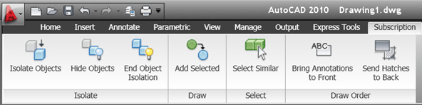
Isolate, Add Selected, Select Similar is something that been found in verticals earlier and as 3:rd party tools.
With Isolate Objects, Hide Objects and End Object Isolation you get more freedom on visibility of objects that extends beyond layers.
There are also two Draw Order tools: Bring Annotations to Front, Send Hatches to Back.
References
If you want to participate in the Beta testing for the next release of AutoCAD visit http://beta.autodesk.com/.
![]()