
AutoCAD 2010 ('twenty ten') was released and shipped on Tuesday, 24 March 2009. AutoCAD 2010 Update 1 (SP1) is available.
Previous AutoCAD version AutoCAD 2009 and newer version AutoCAD 2011.
![]()
New and/or enhanced functions
New and/or enhanced functions and some bug fixes.
![]() New file format "AutoCAD 2010" and is likely to be used for AutoCAD 2011 and AutoCAD 2012. Last file format change was in AutoCAD 2007. The version number is 18.0 and the internal DWG and DXF version is AC1024. It is possible to save to earlier formats down to R14 DWG and R12 DXF.
New file format "AutoCAD 2010" and is likely to be used for AutoCAD 2011 and AutoCAD 2012. Last file format change was in AutoCAD 2007. The version number is 18.0 and the internal DWG and DXF version is AC1024. It is possible to save to earlier formats down to R14 DWG and R12 DXF.
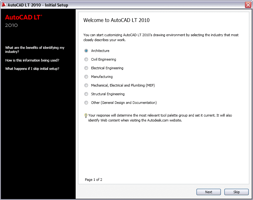
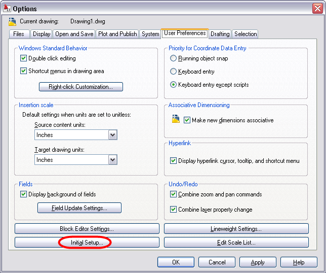
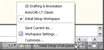
Initial Setup is displayed the first time you start AutoCAD 2010 and allow you to select the industry that most closely describes your work like Architecture or Civil Engineering for example. Depending on your choices the following will be set: the default settings of various AutoCAD functionality, including drawing templates, Autodesk® Seek filters, Autodesk Developer Network partners, the Unified Online Experience portal, and workspaces. If you later want to access Initial Setup it is available via Options>User Preferences.
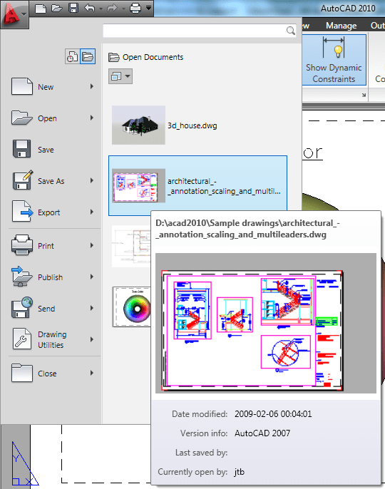
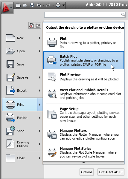
Application Menu has been changed a lot compared to AutoCAD 2009's Menu Browser. There is no longer access to pull-down menus from here. Some name changes have been done. Publish command is known as Batch Plot and available via the Print menu. The Publish menu have access to Send to 3D Print Service and Archive but if you click directly on the Publish menu the publish command is launched.
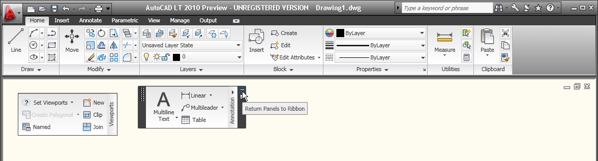
The ribbon has been updated. You can drag a ribbon panel off the ribbon to display it as a sticky panel. Sticky panels remain displayed, even when selecting a different tab, until you select the option to Return Panels to Ribbon.
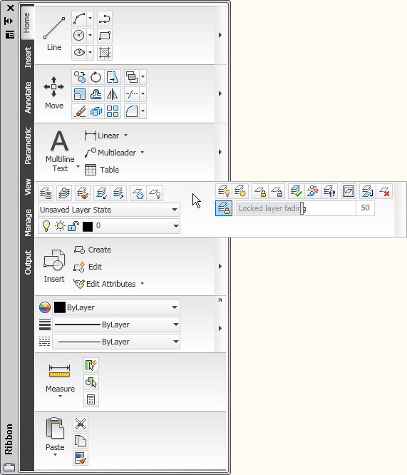
The vertical ribbon has been updated to show the tab names along the side. The panel titles are displayed by default and those with additional tools include slide-out panels. When resizing the vertical ribbon, buttons automatically flow to the next or previous row and other elements, such as slider bars, automatically shorten or lengthen.
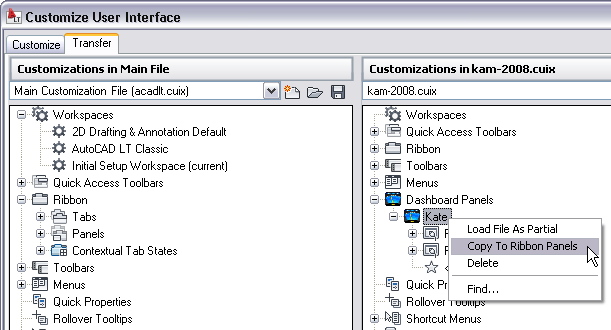
Custom dashboard panels can be converted to new ribbon panels using the Transfer tab in the Customize User Interface (CUI) Editor.
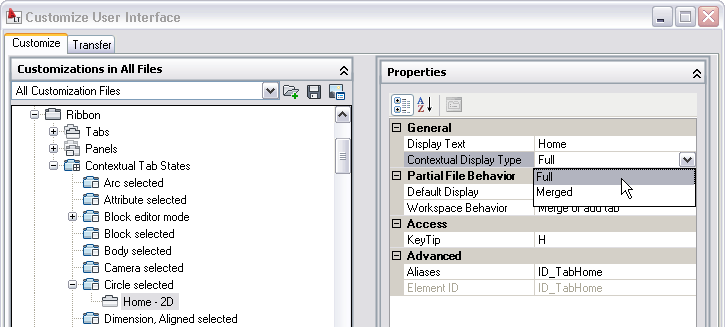
You can customize contextual ribbon tab states which control the display of ribbon tabs and panels based on either the type of object selected in the drawing window or the active command. You can display a ribbon tab that is assigned to a ribbon contextual tab state either on its own tab or with its panels merged onto each of the ribbon tabs in the current workspace. To add a ribbon tab, drag it from the Tabs node in the Customizations In pane to the contextual tab state. For example, if you want the Home tab to become active whenever you select an Arc object, drag the Home-2D ribbon tab to the Arc selected node under the Contextual Tab States. Select it and modify its display type to indicate if it should be displayed as its own tab or merged onto each ribbon tab.
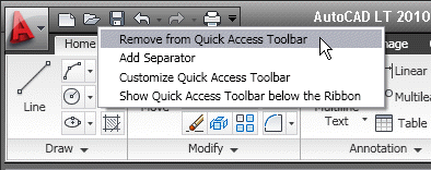
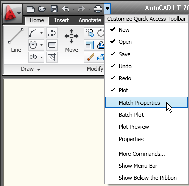
The Quick Access toolbar has been enhanced with more functionality and to ensure consistency with other Windows applications. The Undo and Redo tools include history support and the right-click menu includes new options that enable you to easily remove tools from the toolbar, add separators between tools, and display the Quick Access toolbar above or below the ribbon.
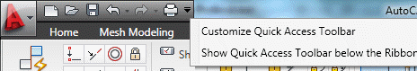
The Quick Access toolbar includes a new flyout menu, which displays a list of common tools that you can select to include in the Quick Access toolbar. The flyout menu provides easy access to additional tools using the Command List pane in the CUI Editor. Other options enable you to show the menu bar or display the Quick Access toolbar below the ribbon.
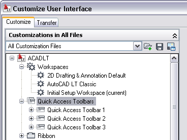
The Quick Access toolbar can be customized using the new Quick Access toolbars node in the CUI Editor. Multiple versions of the Quick Access toolbar can be created and added to different workspaces.
The New Features Workshop has been updated to include AutoCAD 2010 functionality.

Parametric Drawing
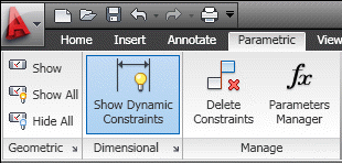
Parametric drawing functionality enables you to constraining drawing objects based on design intent. Geometric and dimensional constraints help ensure that specific relationships and measurements remain persistent even as objects are modified. The tools for creating and managing geometric and dimensional constraints are available on the Parametric ribbon tab, which is automatically displayed in the 2D Drafting and Annotation workspace.
Geometric constraints establish and maintain geometric relationships between objects, key points on objects, or between an object and the coordinate system. Pairs of key points on or between objects can also be constrained to be vertical or horizontal relative to the current coordinate system. For example, you could specify that two circles must always be concentric, that two lines are always parallel, or that one side of a rectangle is always horizontal.
Geometric relationships are defined with geometric constraints, located on the Geometric Panel of the Parametric tab of the ribbon, or with the GEOMCONSTRAINT command. When applying constraints, an icon appears next to the cursor to help you remember which constraint you selected.
When applying a constraint to points, a temporary marker identifies the closest valid point when rolling over an object. It generally corresponds with points that can be used as object snaps.
Whether selecting objects or points on objects to constrain, the order and pick location affects how the objects update: the second object selected updates to satisfy the constraint. After the constraint is applied, though, either object will update when the other is modified.
You can significantly automate the process of applying constraints using the AutoConstrain functionality, available on the Geometric panel of the Parametric tab. AutoConstrain automatically applies constraints to geometry that falls within specified tolerances. For example, applying AutoConstrain to a rectangle consisting of four lines generates the appropriate coincident, horizontal, parallel, and perpendicular constraints to maintain the rectangular shape through various edits. You can control which constraints are available, in what order they are applied, and a tolerance to determine whether constraints are automatically applied. These controls are available on the AutoConstrain tab of the Constraint Settings dialog box, which you can access from the Parametric tab or using the CONSTRAINTSETTINGS command.

Constraint bars show the constraints applied to an object. You can control the display of constraint bars using the CONSTRAINTBAR command or the Show, Show All, and Hide All options on the Geometric panel of the Parametric ribbon tab.
When constraint bars are displayed, you can pass the cursor over a constraint to view the constraint name and the objects that it affects.
You can further control the display of constraint bars on the Geometric tab of the Constraint Settings dialog box. Options include the ability to individually specify which types of constraints can be displayed in the constraint bar, apply transparency, and automatically show the constraint bars after applying constraints to selected objects regardless of the current constraint bar visibility setting.
Establishing Dimensional Relationships
Dimensional relationships put limits on measurements of geometry. For example, you could use a dimensional constraint to specify the radius of an arc, the length of a line, or that two parallel lines are always 15 mm apart. Changing the value of a dimensional constraint forces a change in geometry.
You can create dimensional constraints from the Dimensional panel of the Parametric tab or with the DIMCONSTRAINT command. There are seven types of dimensional constraints, similar to the different kinds of dimensions: Linear, Aligned, Horizontal, Vertical, Angular, Radial, and Diameter. In fact, you can use the DIMCONSTRAINT command to convert a traditional dimension to the corresponding dimensional constraint.
Dimensional constraints are assigned a name when created. The text of a dimensional constraint can display its name, value, or its name and expression (name = formula or equation or value). A “lock” icon appears next to all dimensional constraints to help you visually distinguish them from regular dimensions. By default, dimensional constraints are displayed with a fixed system style that is zoom-invariant—it stays the same size relative to the screen when you zoom in and out so it is always readable.
You can control the display of dimensional constraints, including the visibility of the lock icon, from the Dimensional tab of the Constraint Settings dialog box.
Easily edit a dimensional constraint using grips or by double-clicking on the dimension text to enter values. When you double-click, the constraint name and expression are automatically displayed regardless of the constraint format setting. You can enter just a value, or a name and value using the format name=value (for example, Width=1.5 or Width=Length/3). You can rename dimensional constraints, and use those names in formulas to set the values of other constraints. For example, if you have a rectangle with constraints named “length” and “width,” you could define the value of “width” as “length/3” to constrain the rectangle’s width to 1/3 of its length.
The Parameters Manager, available from the ribbon, enables you to manage dimensional parameters as well as create and manage user-defined parameters. You can provide a meaningful name for the parameter and then assign a numeric value or formula as its expression. A parameter’s expression can reference other parameters so that its value automatically updates when the other parameter values change.
Dimensional constraints can take one of two forms: Annotational or Dynamic. Both forms control geometry in the same way, but they differ in their appearance and they way they are managed.
Dynamic dimensional constraints are not intended to be used as plotted annotation and they have a predefined style that cannot be modified. The display height is controlled by the BPARAMETERSIZE system variable. The visibility of dynamic constraints can be controlled in a variety of ways. First, you can show or hide all dynamic constraints with two icons on the ribbon. Second, even if dynamic constraints are hidden, you can choose to display them when a constrained object is selected, by using the checkbox in the Constraint Settings dialog or the DYNCONSTRAINTMODE system variable. Finally, even if dynamic constraints are set to “Show All,” they will only appear if at least one of the constrained objects is visible (on a layer which is On and Thawed).
Annotational constraints look just like dimension objects, and are managed the same way. They have all the same properties as regular dimensions, including Style. Annotational constraints are intended to be used for plotted dimensional constraints.
You can specify which constraint form is applied by default using the CCONSTRAINTFORM system variable. Additionally, you can specify the constraint form when using the DIMCONSTRAINT command to create a new dimensional constraint. Even after you have created a dimensional constraint, you can easily change its constraint form using the Properties palette.
Dynamic Blocks
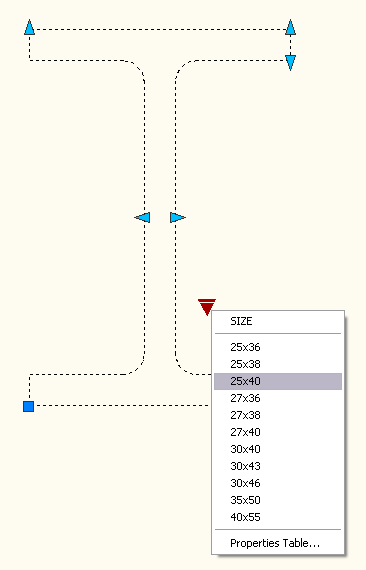
Dynamic Blocks supports geometric and dimensional constraints. They also support the ability to define a table of variations of the dynamic block.
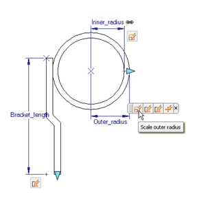
Constraint Parameters behave like dimensional constraints but also expose their name as a property for the block reference similar to dynamic block parameters. You can access constraint parameters from the Dimensional panel of the Block Editor tab in the ribbon or with the BCPARAMETER command. Constraint parameter options include Linear, Aligned, Horizontal, Vertical, Angular, Radial, and Diameter.
Construction geometry (BCONSTRUCTION command) enables you to convert existing objects to construction geometry. The construction geometry is visible in the Block Editor and can be constrained, but it does not display or plot in the block reference.
The Parameters Manager is available in the Block Editor. It lists user parameters, legacy action parameters, block constraint parameters, and attributes. Using the Parameters Manager, you can control whether or not a parameter is displayed in the Properties palette for a selected block reference and you can specify the order in which the parameters appear.
The Test Block tool (BTESTBLOCK command) enables you to test a block definition while authoring dynamic blocks. When you use this tool, AutoCAD opens a temporary window, similar to a drawing window, with the block reference already inserted. The Test Block Window is easily identifiable by the title bar, background color, and the contextual ribbon tab which includes a button to Close Test Block. When you close the test block, you’re automatically returned to the Block Editor.
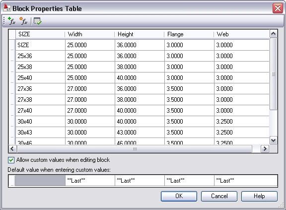
The Block Table tool is accessible from the Dimensional panel of the ribbon, or the BTABLE command, it displays the Block Properties Table where you can define different variations of a property set for the block reference. You can enter properties manually or copy and paste from a Microsoft® Office Excel® spreadsheet.
Action Bars
The display and positioning of Action objects in the Block Editor is enhanced to be consistent with Constraint bars. Action objects are no longer placed individually in the Block Editor; rather they are automatically grouped into Action bars based on the parameters with which they are associated. You can toggle between the new and old display styles by setting the BACTIONBARMODE system variable prior to entering the Block Editor. When viewing the block definition with Action bars turned on, you can quickly tell which actions are associated with which parameters and how many actions each of the parameters affects. You can also see which parameter has its “Chain actions” property enabled. If you roll over an action in an Action bar, both the associated parameter and affected geometry are highlighted.
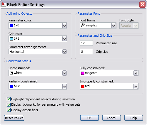
Block Editor Settings is launched with the command BESETTINGS and enables you to control all the settings for the Block Editor environment in one place. You can apply colors to objects based on their constraint status, making it easy to identify objects that are partially, fully, or over-constrained, or that have no constraints at all. The system variable BCONSTATUSMODE controls whether this shading is used.
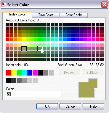
Color Selection - you can set layer colors and pick from the AutoCAD Color Index with ease. Access the Select Color dialog box directly from the Layer drop-down list by selecting on the layer color swatch. If the layer has a viewport color override, the color swatch has a white border. The new color you select applies to the appropriate viewport color override or global color.
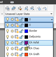
Behavior within the Select Color dialog box has also been improved. As you hover the cursor over a color swatch, the arrow cursor and a black border are displayed in addition to the traditional white border making it easier to see which swatch you are about to select.
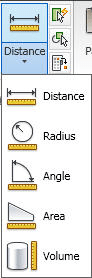 Measure Tools - The new MEASUREGEOM command enables you to measure the distance, radius, angle, area, or volume of a selected object or a sequence of points. You can access these tools from the Utilities panel of the Home ribbon tab. The default option is Distance. However, selecting a different measure tool will set it as the default for the remainder of the AutoCAD session or until a different tool is selected.
The Distance tool enables you to measure the distance between two points. AutoCAD visually displays the distance, delta x, delta y, and angle in the xy plane within the Drawing Editor. If you select the Multiple option, you can continue picking points and, with each pick, AutoCAD displays the cumulative distance. Other options within the Distance tool are similar to the Polyline command enabling you to switch between Line and Arc measuring modes.
You can use the Radius tool to display the radius of a selected arc or circle. The Angle tool measures the angle of a specified arc, circle, line, or vertex.
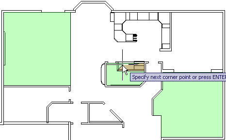
The Area tool enables you to specify points or select objects to display the included area. You can use the Add or Subtract options to determine cumulative areas. As you specify points or select objects, the included area dynamically highlights so that you can see what you’ve selected! Additional options within the Area tool enable you to switch between line and arc measuring tools so that you can easily measure curved spaces as well as polygonal.
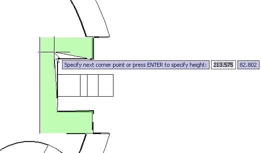
You can use the Volume tool to specify boundary points with visual feedback similar to the Area option, and then specify a height to determine the volume. Additionally, you can display the volume of selected solids or regions.
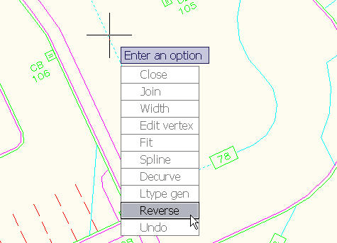
Reverse Tools - reverse the direction of lines, polylines, splines, and helixes.
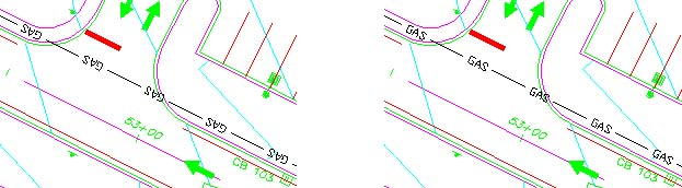
Reverse is also an option in the Pedit command.
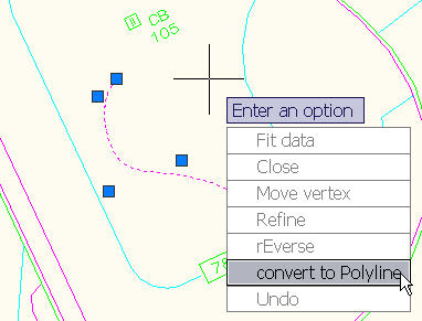
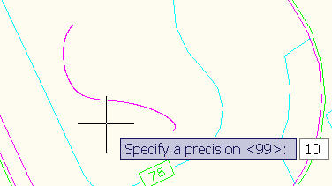
Spline Editing Tools - convert the SPLINE to a POLYLINE. If a SPLINE is selected in the PEDIT command, you get the option to convert it to a POLYLINE. Precision can be specified between 0 and 99 where 99 is the most accurate. If PEDITACCEPT is set to 1, the SPLINE is automatically converted. DELOBJ system variable is honored.
To further control the accuracy when converting splines to polylines, you can use the new PLINECONVERTMODE variable to specify the fit method. When PLINECONVERTMODE is set to 0, polylines are created with linear segments. When it’s set to 1 (the default), polylines are created with arc segments.
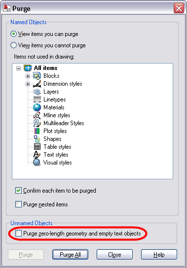
Purge Tools - The Purge dialog box has been updated to include an option for purging zero-length geometry and empty text objects. After performing the Purge operation, AutoCAD will report how many zero-length or empty text objects it purged. The same functionality is available at the Command line using the -PURGE command.
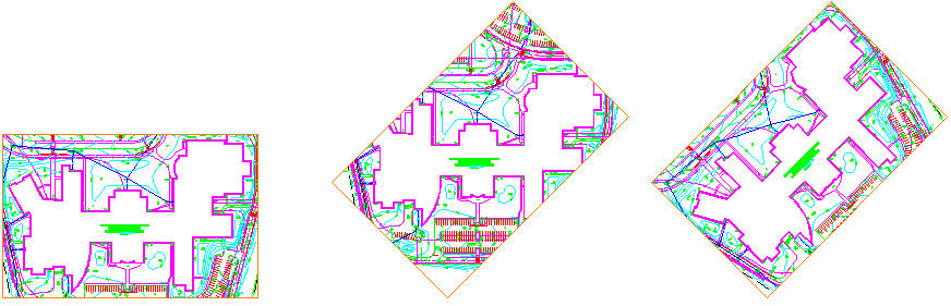
Viewport Rotation Tools - The new VPROTATEASSOC variable enables you to control the rotation of a view within a layout viewport. When you rotate the viewport with VPROTATEASSOC set to 1 (the default), the view will also rotate to maintain its orientation relevant to the viewport. When it’s set to 0, the view within the viewport will not rotate even though the viewport itself does.
External References - consolidated interface and increased flexibility for working with externally referenced file formats, including DWG, DWF, DGN, PDF, and Image files.
Attach externally referenced drawing files using geographic data. If both the host drawing and the external reference drawing have a geographic location, a new option in the External References dialog box enables you to locate the attached xref relative to the host drawing using Geographic Data. A similar option is available in the Insert dialog box.
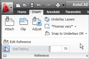
The Reference panel on the Insert tab of the ribbon provides tools for you to attach and modify externally referenced files. Use the Attach tool to select a DWG, DWF, DGN, PDF, or Image file and specify attachment options. Additional tools enable you to clip a selected reference, adjust its Fade, Contrast, and Brightness, control its layer visibility, display reference frames, snap to underlay geometry, and adjust xref fading.

When you select a reference file in the drawing, a relevant contextual tab is automatically displayed in the ribbon. For example, if you select a PDF underlay, the PDF Underlay tab is displayed providing you easy access to PDF underlay tools.
Easily edit the clip boundary of any reference using grips. You can even invert the clip with a simple click on the invert grip.
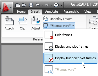
You can display the reference frame for each type of reference using its specific frame system variables such as DWFFRAME, DGNFRAME, and PDFFRAME. To quickly override these individual system variables, use the Frame tool (FRAME system variable) in the References panel of the Insert ribbon tab. You can hide frames, display and plot them, or display but not plot them.
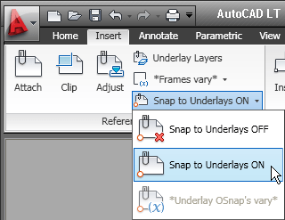
You can enable object snapping for geometry in underlay files. To control this behavior for specific reference types, use its individual system variables such as DWFOSNAP, DGNOSNAP, and PDFOSNAP. You can override these individual system variables using the Snap to Underlays tool (UOSNAP system variable) in the References panel of the Insert ribbon tab.
When you open a drawing that has unresolved references, a new tool helps identify the missing files.
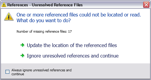
If you choose Update, AutoCAD opens the External References palette so you can repath the missing files. If you choose Ignore, the warning closes and takes no action. If you always want to ignore unresolved references, use the checkbox at the bottom to stop the warning from displaying again.
This is a great improvement over previous versions, when you had to manually search for missing references by checking the command line when opening a file, scouring the drawing for the text strings identifying unresolved references, or looking in the External References palette.
Sheet Sets - Sheet set functionality includes a variety of enhancements to increase productivity.
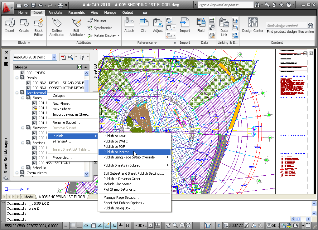
A new Sheet right-click menu option enables you to quickly specify whether a sheet should be included in the publish operation. To control the publish property of multiple sheets and even entire subsets, you can access the new Publish Sheets dialog box from the right-click menu by selecting the option to Edit Subset and Sheet Publish Settings.
The Subset Properties dialog box has a new look and feel, similar to the Sheet Set Properties and Sheet Properties dialog boxes. It includes a new control to specify if the subset should honor the sheets’ individual “Include for Publish” settings or if it, the entire subset, should be excluded from the publish operation. The Subset right-click menu includes similar options. An icon in the sheet list provides a visual indication of those subsets that are excluded from the Publish operation.
Sheet List Table functionality is more flexible. In addition to creating a sheet list table for the entire sheet set, you can now insert a sheet list table for individual subsets and even individual sheets. You can access this functionality from the right-click menu in the Sheet List table and a new tab in the Sheet List Table dialog box enables you to control the behavior of subsets and sheets. You can specify which sheets to include and which subsets to track so that you are prompted when new sheets are added to that subset.
Quick Views - The preview images for Quick View Layouts and Quick View Drawings have been enhanced to include a preview image of Model space in addition to the layout previews.
PDF Support - PDF support has been significantly enhanced. PDF publishing provides better visual quality with smaller file sizes, and you can even attach PDF files to a drawing as an underlay.
PDF output provides more flexibility and higher quality output than previously available. The default vector resolution has been increased from 400 to 600 dpi to produce precise lineweights at a reasonable file size. To further improve the visual quality of PDF output, TrueType fonts are exported as text rather than as graphics. This improves the visual quality of text and also enables highlighting, searching, and copying text within the PDF viewer. Additional improvements enable you to specify merge control, include layer information, and automatically preview the plotted PDF.
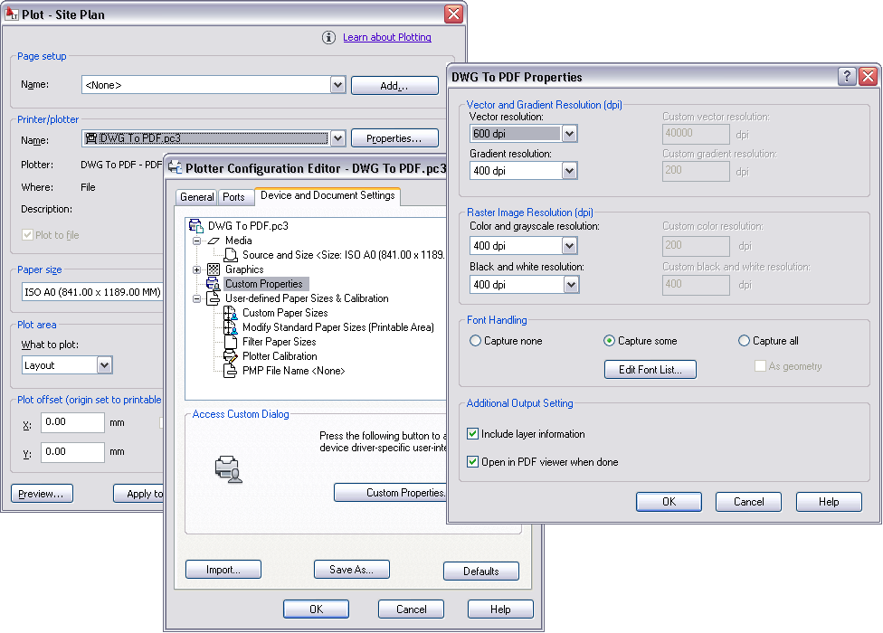
You can use the Plotter Configuration Editor to view and modify the PDF settings for plotted output. Select the DWG to PDF.pc3 plotter in the Plot dialog box and then choose Properties. The new Merge Control option is displayed under the Graphics node and the other options are accessible when you select Custom Properties.
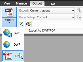
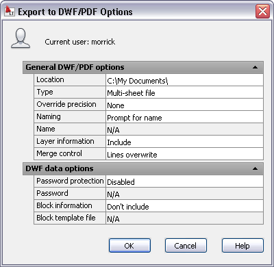
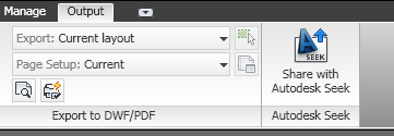
You can control many of the PDF output settings separately for exported, published, or plotted PDF files. A new Export to DWF/PDF panel on the Output ribbon tab provides access to the Export to DWF/PDF Options dialog box where you can specify a single- or multi-sheet PDF file, include layer information, and apply merge control. After applying the appropriate options, you can select PDF from the flyout tools.
In addition to the Plot and Export functionality, PDF support has been integrated into Sheet Sets and Publish. You can specify PDF output, including single- or multi-sheet, layer information, and merge control, in the Sheet Set Publish Options and the Publish Options dialog boxes.

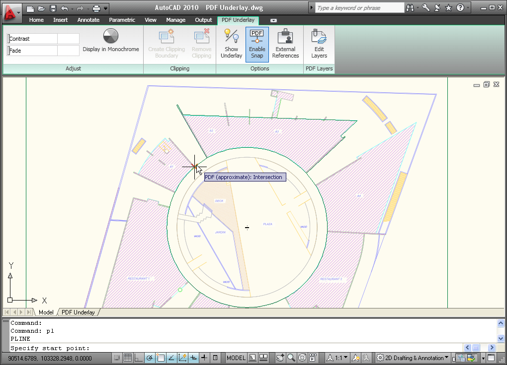
You can attach a PDF file to an AutoCAD drawing as an underlay. You can work with PDF underlays in the same way you work with other external references including DWG, DWF, DGN, and Image files. You can even snap to key points on PDF geometry using familiar object snaps.
File Navigation dialogs such as Open and Save now support auto-complete when typing file names.

Object Size Limits
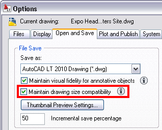
In previous versions of AutoCAD, no single object in an AutoCAD drawing could be larger than 256 MB. In AutoCAD 2010, the object size limit has been increased to at least 4 GB (depending on your system configuration), providing more flexibility. These large objects, however, are not backwards-compatible, so a new compatibility option has been added to the Open and Save tab of the Options dialog box. See the Maintain drawing size compatibility option.
AutoCAD 2010 supports object size limits greater than those available in previous releases. With increased object size limits you can create larger and more complex models. Using increased object size limits can result in compatibility issues with legacy drawing file formats (AutoCAD 2007 and earlier).
When working with drawings that you might need to exchange with others using AutoCAD 2009 and earlier, set the LARGEOBJECTSUPPORT system variable to 0. Setting LARGEOBJECTSUPPORT to 0 warns you when a drawing contains large objects that cannot be opened by a release of the program prior to AutoCAD 2010.
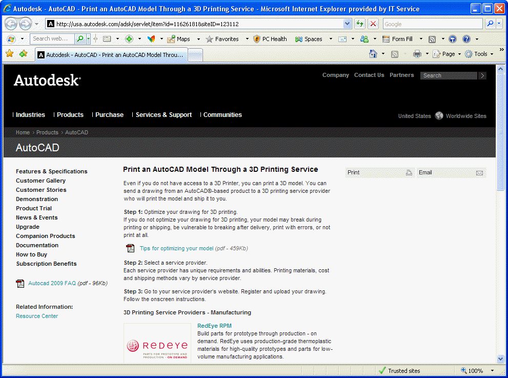
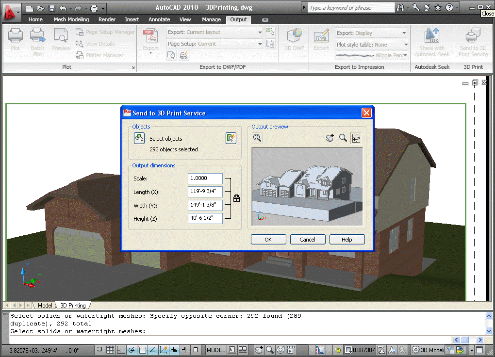
3D Printing - The 3D printing functionality enables you to output your 3D AutoCAD drawings directly to STL-supported 3D printing vendors through an internet connection. This utility will walk you through preparing your model, adjusting the scale, creating an STL file from your model, then downloading your STL file to a user-specified vendor for printing. The final 3D model will be printed then shipped to you within days.
You can prepare your model for 3D printing using the 3DPRINT command or selecting Send to 3D Print Service from the output tab. Select all solid objects you want to print. Once all objects are selected, select Return, which will display the Send to 3D Print Service dialog. Specify the scale of your model, then save the model to an STL format. Once saved, you are automatically directed to a location on Autodesk.com where you can select the 3D print vendor.
eTransmit - The eTransmit functionality has been enhanced to include a new option to “include unloaded file references.” When this option is enabled, all unloaded reference files are included in the transmittal set but will remain unloaded in the eTransmit package. The Archive functionality includes the same option to include unloaded file references and is enabled by default.
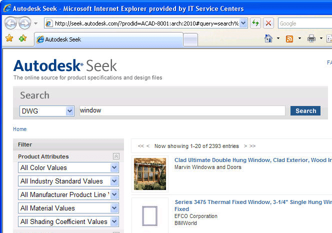
Autodesk Seek - Previously known as “Content Search,” Autodesk Seek is a more efficient online utility that allows users to quickly search product information and designs from the web and download the designs into AutoCAD. For example, if you were designing a home, and wanted to include pre-existing windows, you could look for product specifications and actual 2D and 3D design files on seek.autodesk.com. Search through the results for your desired window specifications, and then download the window file to incorporate it into your design.
Note: Currently Seek is focused on manufacturer-specific building products only, but is considering expanding to manufacturing products.
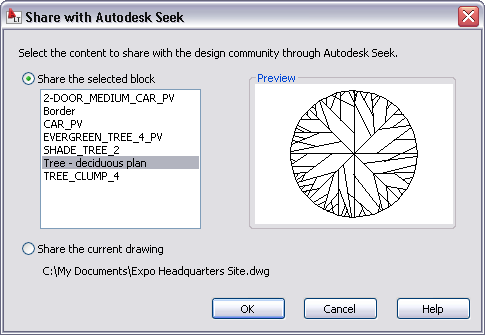
AutoCAD 2010 will also enable vendors to easily upload their designs to Seek using the Share with Autodesk Seek utility. This utility enables product vendors to move their product to the market quicker than ever before, so that AutoCAD designers can specify actual products in their designs.
After an initial setup process with Seek, users can download new designs whenever they wish using the Share with Autodesk Seek tool.
Conceptual and Free-Form Design
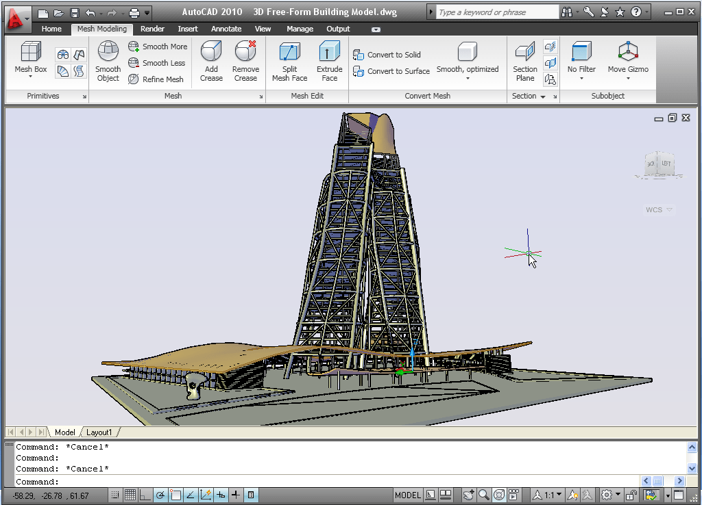
Smooth Mesh tools enable you to create 3D models that are free-form and flowing. The new Mesh Modeling ribbon tab provides easy access to the mesh creation and editing tools. A mesh object can be incrementally smoothed to create curved shapes, even when starting with a traditional primitive shape. The process of creating smooth mesh primitives is similar to creating their solid equivalents. You can adjust the smoothness level as you create the mesh by specifying the Settings option.
You can control the default tessellation divisions for each type of primitive using the Mesh Primitive options, which are accessible with the MESHPRIMITIVEOPTIONS command or from the 3D Modeling tab of the Options dialog box.
You can further control the behavior for converting objects such as solids and surfaces to mesh objects using the Mesh Tessellation Options dialog box, accessible with the MESHOPTIONS command or from the 3D Modeling tab of the Options dialog box.
You can split a mesh face by specifying two split points. You can then select and edit each new face, as well as the edges and vertices that they produce, using the CTRL key for subobject selection. Selecting individual subobjects enables you to further modify the shape of the mesh. In addition, you can apply different materials to individual faces.
Easily extrude a face in a mesh object using the Extrude Face tool on the Mesh Edit panel. Unlike extrusions performed on solid objects (which create a new solid object), mesh face extrusions extend and deform the mesh object without creating a new one.
After using the mesh creating and editing tools to create organic meshes, you can convert those that are watertight (no gaps) and not self-intersecting, to smooth or faceted solids. Additional tools enable you to convert meshes to smooth or faceted surfaces and you can control the smoothness of objects during the conversion process. These conversion tools are available in the Convert Mesh panel of the ribbon tab.
3D Scale Gizmo allow you to easily scale selected objects.
The 3D Move gizmo has been enhanced with longer axes, XYZ labels, and planar highlighting to make it easier for you to view and select the appropriate axis or plane. Save another step using the 3D Move gizmo by picking the constraint axis or plane and the base point in one operation. As you specify the second point, the 3D Move gizmo dynamically moves with the selected objects.
A new context menu, available when you right-click on a gizmo axis or plane, enables you to change the gizmo’s behavior. You can set the constraint to a different axis or plane, switch between the 3D Move, 3D Rotate, and 3D Scale gizmos, relocate the gizmo, and align it to the world UCS, current UCS, or an object face. You can further customize the location and orientation of the gizmo by manually specifying its origin, direction of the X-axis, and position of the XY plane.
In addition to using the right-click menu option to switch gizmos, you can press the space bar to cycle between them. If you want to change the gizmo that displays by default when you select an object, use the gizmo flyout on the ribbon.
Subobject Selection Filters restrict the selection of subobjects to faces, edges, or vertices. You can access these filters from the Subobject panel on the Home tab of the ribbon or from the right-click menu when no objects are selected. With the subobject selection filter set to vertex, for example, you can ensure that when you press CTRL and pick on the corner of an object, AutoCAD will select the vertex rather than the edge.
The Solid Editing panel of the Home tab includes tools to perform unions, subtractions, interferences, intersections, and imprinting. These tools, which were previously available only for solid objects, now work on surfaces as well.
CUIx File - the CUI file is replaced with the new CUIx file format. A CUIx file is a package file format that helps to improve performance when working with the CUI Editor. In addition to typical CUI information, a CUIx file contains the custom images used by the commands defined in the file.
Action Macros - User interface for Action Macros have been simplified for increased usability and efficiency.
The option to “Request User Input” has been renamed to “Pause for User Input” and the corresponding icon has been updated for consistency with the user icons in the Action Tree. The Action tree tooltips and playback behavior are more predictable and consistent when accepting default values by pressing the Enter key and when using dynamic input. In addition, the playback user messages have been streamlined for increased clarity.
A new command enables you to establish base points at specified locations in your action macro. You can access the new ACTBASEPOINT command as a button in the Action Recorder panel or as a right-click menu option in the Action Tree.
A new Action Macro Manager enables you to copy, rename, modify, and delete action macro files from a central location. An Options button in the lower left corner provides quick access to the Action Recorder settings on the Files tab of the Options dialog box. You can launch the Action Macro Manager from the Action Recorder panel in the ribbon as well as from the right-click menu (Action Recorder>Play>Manage Action Macros) when no objects are selected.

Online License Transfer (OLT) Utility that enables you to move stand-alone licenses between computers. It replaces the Portable License Utility (PLU) used in previous Autodesk product releases. You can access OLT functionality from the AutoCAD 2010>License Transfer Utility option in the Start menu.
From the License Transfer Utility, you can choose to export or import a license. Both options require you to log in to Autodesk. You can export a license as either private or public. A private license can be imported only by the person who exported it. A public license can be imported by any user running the same product and serial number.
![]()
Find and Replace - Optional zoom to each found text string. The result or highlighted objects can create a selection set.
Multileaders - Edit the properties of individual Multileader segments by using the CTRL key to select the segment and then accessing the Properties window. New grips at each corner of the leader text enable you to resize the text box in the same way you resize a simple mtext object.
Mleader styles have been enhanced to provide you with more control over the leader connections. On the Leader Structure tab, you can specify Vertical attachment in addition to the traditional Horizontal attachment. On the Content tab, when a Block multileader type is selected, you can specify a scale. The block scale is also displayed as a Multileader property in the Properties window. A new button on the Content tab provides direct access to the Text Style dialog box enabling you to create and modify text styles without exiting the Multileader Style dialog box.
The MLEADEREDIT command has been streamlined by eliminating the need for you to select an option to add or remove leader lines. It adds leaders by default until you select the option to remove leaders.
Mtext improvements include a default column mode of Dynamic with manual height. In addition, the corner grips on mtext objects are now consistent with the corner grips on table objects.
Spell checking - The Check Spelling dialog box has been updated to include an Undo button, which enables you to undo actions you made for the previous spelling mistake. In addition, the Select Objects button has been enhanced so that you can begin selecting objects to check without first having to choose the Select Objects option from the drop-down list.
Dimensions - Enhancements to dimension styles and properties provide more control over the display and placement of dimension text.
The Text tab of the Dimension Style dialog box has been updated with a new text placement option that enables you to position dimension text below the dimension line. You can control the direction of the text using the new View Direction option in which you can specify that the text be displayed from Left-to-Right or Right-to-Left. The Properties palette has been updated to include these new properties as well.
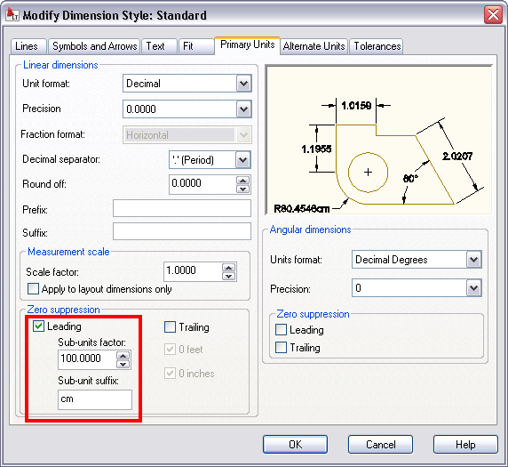
The Primary and Alternate Units tabs of the Dimension Style dialog box include new sub-unit controls for suppression of leading zeros. You can specify a sub-units factor and suffix. For example, if the unit is 1 meter, you could specify a sub-unit factor of 100 and sub-unit suffix of cm. In this case, when the dimension value is less than 1, such as .96, it displays as 96 cm instead of .96 m. The new sub-units properties are also included in the Properties palette.
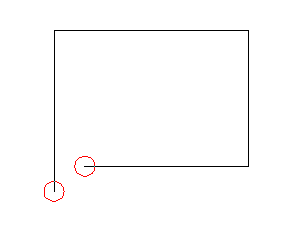
Hatch - When a hatch boundary area is not found, AutoCAD attempts to show you where the problem may have occurred. Red circles appear around endpoints near where any gap in geometry is estimated to be. More robust boundary detection.
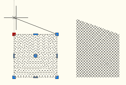
Non-associative hatch objects can now be edited to change their shape.
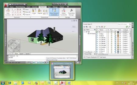
AutoCAD 2010 running on Windows 7.
API news
New API for RibbonBar controls in the CUI.
Windows Presentation Foundation (WPF) is starting to be used for AutoCAD's user interface elements.
Overrule API is available in ObjectARX (C++) and .NET. Overruleed objects are like customized objects, rather than custom objects.
Freeform Modeling API enabling to work with the Sub-division mesh object.
Autodesk TechPubs team are working on the first release of an AutoCAD .NET Developers Guide. It's expect to be available sometime in the summer 2009.
Hardware and software requirements
SSE2 extended instruction set is supported and required so AutoCAD can use the power of modern CPUs better resulting in better speed.
Before you install AutoCAD 2010, make sure that your computer meets the minimum hardware and software requirements.
Whether your Windows operating system is the 32-bit or 64-bit version is automatically detected when installing AutoCAD 2010. The appropriate version of AutoCAD 2010 will be installed. The 32-bit version of AutoCAD 2010 cannot be installed on a 64-bit version of Windows.
It will be possible to run AutoCAD 2010 on Microsoft Windows 7.
See the following tables for hardware and software requirements.
| Description | Requirement |
| Operating system | 32bit: Microsoft® Windows® Vista® Business SP1 Microsoft Windows Vista Enterprise SP1 Microsoft Windows Vista Home Premium SP1 Microsoft Windows Vista Ultimate SP1 Microsoft Windows XP Home SP2 or later Microsoft Windows XP Professional SP2 or later 64bit: Microsoft Windows Vista Business SP1 Microsoft Windows Vista Enterprise SP1 Microsoft Windows Vista Home Premium SP1 Microsoft Windows Vista Ultimate SP1 Microsoft Windows XP Professional x64 Edition SP2 or later For more information on Windows Vista versions please see http://www.microsoft.com/windowsvista/versions It is recommended that non-English language versions of AutoCAD 2010 be installed on an operating system with a user interface language that matches the code page of the AutoCAD 2010 language. A code page provides support for character sets used in different languages. |
| Browser | Windows Internet Explorer® 7.0 or later |
| CPU type | 32bit: Windows Vista: Intel® Pentium® 4 or AMD Athlon® Dual Core, 3.0 GHz or higher with SSE2 technology Windows XP: Intel Pentium 4 or AMD Athlon Dual Core, 1.6 GHz or higher with SSE2 technology 64bit: AMD Athlon® 64 or Opteron® with SSE2 technology; Intel® Pentium® 4 or Xeon® with Intel EM64T support & SSE2 technology |
| Memory | Windows Vista: 2 GB RAM Windows XP: 2 GB RAM |
| Display resolution | 1024 x 768 display with True Color Requires a Windows-supported display adapter. For graphic cards that support Hardware Acceleration, DirectX 9.0c or later must be installed. Installing from the ACAD.msi file does not install DirectX 9.0c or later. You must manually install DirectX to configure Hardware Acceleration. |
| Hard Disk | 32bit: 1 GB free disk space for installation 64bit: 1.5 GB free disk space for installation |
| Pointing Device | MS-Mouse compliant |
| Media (CD ROM vs. DVD) | Download and Installation from DVD or CD-ROM |
| 3D Modeling additional requirements | Intel Pentium 4 or AMD Athlon, 3.0 GHz or greater; Intel or AMD Dual Core, 2.0 GHz or greater 2 GB RAM or greater 2 GB free disk space available not including installation 1280 x 1024 32-bit color video display adapter (True Color) 128 MB or greater, Direct3D®-capable workstation class graphics card |
Additional recommendations for 3D use
| Hardware/Software | Requirement |
| Operating system | 32-bit Microsoft Windows Vista Enterprise Microsoft Windows Vista Business Microsoft Windows Vista Ultimate Microsoft Windows Vista Home Premium Microsoft Windows XP Professional Edition (SP2) Microsoft Windows XP Home Edition (SP2) 64-bit Microsoft Windows Vista Enterprise Microsoft Windows Vista Business Microsoft Windows Vista Ultimate Microsoft Windows Vista Home Premium Microsoft Windows XP Professional Edition (SP2) It is recommended that non-English language versions of AutoCAD 2010 be installed on an operating system with a user interface language that matches the code page of the AutoCAD 2010 language. A code page provides support for character sets used in different languages. Whether the Microsoft Windows operating system is the 32-bit or the 64-bit version is automatically detected when installing AutoCAD 2010. The appropriate version of AutoCAD 2010 will be installed. The 32-bit version of AutoCAD 2010 cannot be installed on a 64-bit version of Microsoft Windows. |
| Processor | Intel Pentium 4 processor or AMD Athlon, 2.2 GHz or greater or AMD Dual Core processor, 1.6 GHz or greater |
| RAM | 2 GB (or greater) |
| Graphics card | 1280 x 1024 32-bit color video display adapter (True Color) 128 MB or greater, OpenGL, or Direct3D capable workstation class graphics card. For Microsoft Windows Vista, a Direct3D capable workstation class graphics card with 128 MB or greater is required 1024 x 768 VGA with True Color (minimum) Requires a Windows-supported display adapter. For graphic cards that support Hardware Acceleration, DirectX 9.0c or later must be installed. Installing from the ACAD.msi file does not install DirectX 9.0c or later. You must manually install DirectX to configure Hardware Acceleration. For more information about tested and certified graphics cards, visit http://www.autodesk.com/autocad-graphicscard |
| Hard disk | 2 GB (in addition to the 1GB or above required for installation) |
Note Adobe Flash Player is no longer installed by default. If a suitable version of Flash is not currently installed on your system, a message requests that you download it from Adobe’s website. If you do not have Internet access, you can also access the Flash installer on the AutoCAD 2010 product media.
ActiveX API
ActiveX API
Enums
AcEntityName (Changed)
        acSubDMesh = 49 (New)
        acPdfUnderlay = 50 (New)
AcPlotScale (Changed)
        ac1_8 = 19 (Removed)
        ac1_10 = 20 (Removed)
        ac1_16 = 21 (Removed)
        ac1_20 = 22 (Removed)
        ac1_30 = 23 (Removed)
        ac1_40 = 24 (Removed)
        ac1_50 = 25 (Removed)
        ac1_100 = 26 (Removed)
        ac2_1 = 27 (Removed)
        ac4_1 = 28 (Removed)
        ac8_1 = 29 (Removed)
        ac10_1 = 30 (Removed)
        ac100_1 = 31 (Removed)
        ac1_5 = 19 (New)
        ac1_8 = 20 (New)
        ac1_10 = 21 (New)
        ac1_16 = 22 (New)
        ac1_20 = 23 (New)
        ac1_30 = 24 (New)
        ac1_40 = 25 (New)
        ac1_50 = 26 (New)
        ac1_100 = 27 (New)
        ac2_1 = 28 (New)
        ac4_1 = 29 (New)
        ac8_1 = 30 (New)
        ac10_1 = 31 (New)
        ac100_1 = 32 (New)
AcDimVerticalJustification (Changed)
        acUnder = 4 (New)
AcViewportScale (Changed)
        acVp1 = 2 (Removed)
        acVp2 = 3 (Removed)
        acVp3 = 4 (Removed)
        acVp4 = 5 (Removed)
        acVp5 = 6 (Removed)
        acVp6 = 7 (Removed)
        acVp7 = 8 (Removed)
        acVp8 = 9 (Removed)
        acVp9 = 10 (Removed)
        acVp10 = 11 (Removed)
        acVp11 = 12 (Removed)
        acVp12 = 13 (Removed)
        acVp13 = 14 (Removed)
        acVp14 = 15 (Removed)
        acVp15 = 16 (Removed)
        acVp16 = 17 (Removed)
        acVp17 = 18 (Removed)
        acVp18 = 19 (Removed)
        acVp19 = 20 (Removed)
        acVp20 = 21 (Removed)
        acVp21 = 22 (Removed)
        acVp22 = 23 (Removed)
        acVp23 = 24 (Removed)
        acVp24 = 25 (Removed)
        acVp25 = 26 (Removed)
        acVp26 = 27 (Removed)
        acVp27 = 28 (Removed)
        acVp28 = 29 (Removed)
        acVp29 = 30 (Removed)
        acVp30 = 31 (Removed)
        acVp31 = 32 (Removed)
        acVp32 = 33 (Removed)
        acVp33 = 34 (Removed)
        acVp34 = 35 (Removed)
        acVp35 = 36 (Removed)
        acVp36 = 37 (Removed)
        acVp37 = 38 (Removed)
        acVp38 = 39 (Removed)
        acVp39 = 40 (Removed)
        acVp40 = 41 (Removed)
        acVp41 = 42 (Removed)
        acVp42 = 43 (Removed)
        acVp43 = 44 (Removed)
        acVp44 = 45 (Removed)
        acVp45 = 46 (Removed)
        acVp46 = 47 (Removed)
        acVp47 = 48 (Removed)
        acVp48 = 49 (Removed)
        acVp49 = 50 (Removed)
        acVp50 = 51 (Removed)
        acVp51 = 52 (Removed)
        acVp52 = 53 (Removed)
        acVp53 = 54 (Removed)
        acVp54 = 55 (Removed)
        acVp55 = 56 (Removed)
        acVp56 = 57 (Removed)
        acVp57 = 58 (Removed)
        acVp58 = 59 (Removed)
        acVp59 = 60 (Removed)
        acVp60 = 61 (Removed)
        acVp61 = 62 (Removed)
        acVp62 = 63 (Removed)
        acVp63 = 64 (Removed)
        acVp64 = 65 (Removed)
        acVp65 = 66 (Removed)
        acVp66 = 67 (Removed)
        acVp67 = 68 (Removed)
        acVp68 = 69 (Removed)
        acVp69 = 70 (Removed)
        acVp70 = 71 (Removed)
        acVp71 = 72 (Removed)
        acVp72 = 73 (Removed)
        acVp73 = 74 (Removed)
        acVp74 = 75 (Removed)
        acVp75 = 76 (Removed)
        acVp76 = 77 (Removed)
        acVp77 = 78 (Removed)
        acVp78 = 79 (Removed)
        acVp79 = 80 (Removed)
        acVp80 = 81 (Removed)
        acVp81 = 82 (Removed)
        acVp82 = 83 (Removed)
        acVp83 = 84 (Removed)
        acVp84 = 85 (Removed)
        acVp85 = 86 (Removed)
        acVp86 = 87 (Removed)
        acVp87 = 88 (Removed)
        acVp88 = 89 (Removed)
        acVp89 = 90 (Removed)
        acVp90 = 91 (Removed)
        acVp91 = 92 (Removed)
        acVp92 = 93 (Removed)
        acVp93 = 94 (Removed)
        acVp94 = 95 (Removed)
        acVp95 = 96 (Removed)
        acVp96 = 97 (Removed)
        acVp97 = 98 (Removed)
        acVp98 = 99 (Removed)
        acVp99 = 100 (Removed)
        acVp100 = 101 (Removed)
        acVp1_8 = 5 (Removed)
        acVp1_10 = 6 (Removed)
        acVp1_16 = 7 (Removed)
        acVp1_20 = 8 (Removed)
        acVp1_30 = 9 (Removed)
        acVp1_40 = 10 (Removed)
        acVp1_50 = 11 (Removed)
        acVp1_100 = 12 (Removed)
        acVp2_1 = 13 (Removed)
        acVp4_1 = 14 (Removed)
        acVp8_1 = 15 (Removed)
        acVp10_1 = 16 (Removed)
        acVp100_1 = 17 (Removed)
        acVp1_128in_1ft = 18 (Removed)
        acVp1_64in_1ft = 19 (Removed)
        acVp1_32in_1ft = 20 (Removed)
        acVp1_16in_1ft = 21 (Removed)
        acVp3_32in_1ft = 22 (Removed)
        acVp1_8in_1ft = 23 (Removed)
        acVp3_16in_1ft = 24 (Removed)
        acVp1_4in_1ft = 25 (Removed)
        acVp3_8in_1ft = 26 (Removed)
        acVp1_2in_1ft = 27 (Removed)
        acVp3_4in_1ft = 28 (Removed)
        acVp1in_1ft = 29 (Removed)
        acVp1and1_2in_1ft = 30 (Removed)
        acVp3in_1ft = 31 (Removed)
        acVp6in_1ft = 32 (Removed)
        acVp1ft_1ft = 33 (Removed)
        acVp1_5 = 5 (New)
        acVp1_8 = 6 (New)
        acVp1_10 = 7 (New)
        acVp1_16 = 8 (New)
        acVp1_20 = 9 (New)
        acVp1_30 = 10 (New)
        acVp1_40 = 11 (New)
        acVp1_50 = 12 (New)
        acVp1_100 = 13 (New)
        acVp2_1 = 14 (New)
        acVp4_1 = 15 (New)
        acVp8_1 = 16 (New)
        acVp10_1 = 17 (New)
        acVp100_1 = 18 (New)
        acVp1_128in_1ft = 19 (New)
        acVp1_64in_1ft = 20 (New)
        acVp1_32in_1ft = 21 (New)
        acVp1_16in_1ft = 22 (New)
        acVp3_32in_1ft = 23 (New)
        acVp1_8in_1ft = 24 (New)
        acVp3_16in_1ft = 25 (New)
        acVp1_4in_1ft = 26 (New)
        acVp3_8in_1ft = 27 (New)
        acVp1_2in_1ft = 28 (New)
        acVp3_4in_1ft = 29 (New)
        acVp1in_1ft = 30 (New)
        acVp1and1_2in_1ft = 31 (New)
        acVp3in_1ft = 32 (New)
        acVp6in_1ft = 33 (New)
        acVp1ft_1ft = 34 (New)
AcTextAttachmentDirection (New)
        acAttachmentHorizontal = 0
        acAttachmentVertical = 1
AcVerticalTextAttachmentType (New)
        acAttachmentCenter = 0
        acAttachmentLinedCenter = 1
AcMeshCreaseType (New)
        acNoneCrease = 0
        acAlwaysCrease = 1
        acCreaseByLevel = 2Classes
IAcadBlock (Changed)
        AddMLeader - Method (Moved from IAcadBlock2)
IAcadAttribute (Changed)
        MTextAttribute - Property
              (Moved from IAcadAttribute2)
        MTextAttributeContent - Property
              (Moved from IAcadAttribute2)
        UpdateMTextAttribute - Method
              (Moved from IAcadAttribute2)
        MTextBoundaryWidth - Property
              (Moved from IAcadAttribute2)
        MTextDrawingDirection - Property
              (Moved from IAcadAttribute2)
IAcadDimAligned (Changed)
        DimConstrForm - Property (New)
        DimConstrReference - Property (New)
        DimConstrName - Property (New)
        DimConstrExpression - Property (New)
        DimConstrValue - Property (New)
        DimConstrDesc - Property (New)
        SubUnitsSuffix - Property (New)
        SubUnitsFactor - Property (New)
        AltSubUnitsSuffix - Property (New)
        AltSubUnitsFactor - Property (New)
IAcadDimension (Changed)
        DimTxtDirection - Property (New)
IAcadDimAngular (Changed)
        DimConstrForm - Property (New)
        DimConstrReference - Property (New)

        DimConstrName - Property (New)
        DimConstrExpression - Property (New)
        DimConstrValue - Property (New)
        DimConstrDesc - Property (New)
IAcadDimDiametric (Changed)
        DimConstrForm - Property (New)
        DimConstrReference - Property (New)
        DimConstrName - Property (New)
        DimConstrExpression - Property (New)
        DimConstrValue - Property (New)
        DimConstrDesc - Property (New)
IAcadDimRotated (Changed)
        DimConstrForm - Property (New)
        DimConstrReference - Property (New)
        DimConstrName - Property (New)
        DimConstrExpression - Property (New)
        DimConstrValue - Property (New)
        DimConstrDesc - Property (New)
        SubUnitsSuffix - Property (New)
        SubUnitsFactor - Property (New)
        AltSubUnitsSuffix - Property (New)
        AltSubUnitsFactor - Property (New)
IAcadDimOrdinate (Changed)
        SubUnitsSuffix - Property (New)
        SubUnitsFactor - Property (New)
        AltSubUnitsSuffix - Property (New)
        AltSubUnitsFactor - Property (New)
IAcadDimRadial (Changed)
        DimConstrForm - Property (New)
        DimConstrReference - Property (New)
        DimConstrName - Property (New)
        DimConstrExpression - Property (New)
        DimConstrValue - Property (New)
        DimConstrDesc - Property (New)
IAcadDim3PointAngular (Changed)
        DimConstrForm - Property (New)
        DimConstrReference - Property (New)
        DimConstrName - Property (New)
        DimConstrExpression - Property (New)
        DimConstrValue - Property (New)
        DimConstrDesc - Property (New)
IAcadTable (Changed)
        IsEmpty - Method (Moved from IAcadTable2)
        CreateContent - Method (Moved from IAcadTable2)
        MoveContent - Method (Moved from IAcadTable2)
        DeleteContent - Method (Moved from IAcadTable2)
        GetValue - Method (Moved from IAcadTable2)
        SetValue - Method (Moved from IAcadTable2)
        SetValueFromText - Method (Moved from IAcadTable2)
        GetDataFormat - Method (Moved from IAcadTable2)
        SetDataFormat - Method (Moved from IAcadTable2)
        GetTextString - Method (Moved from IAcadTable2)
        SetTextString - Method (Moved from IAcadTable2)
        GetFieldId2 - Method (Moved from IAcadTable2)
        SetFieldId2 - Method (Moved from IAcadTable2)
        GetBlockTableRecordId2 - Method
              (Moved from IAcadTable2)
        SetBlockTableRecordId2 - Method
              (Moved from IAcadTable2)
        GetBlockAttributeValue2 - Method
              (Moved from IAcadTable2)
        SetBlockAttributeValue2 - Method
              (Moved from IAcadTable2)
        GetCustomData - Method (Moved from IAcadTable2)
        SetCustomData - Method (Moved from IAcadTable2)
        GetCellStyle - Method (Moved from IAcadTable2)
        SetCellStyle - Method (Moved from IAcadTable2)
        GetContentColor2 - Method (Moved from IAcadTable2)
        SetContentColor2 - Method (Moved from IAcadTable2)
        GetDataType2 - Method (Moved from IAcadTable2)
        SetDataType2 - Method (Moved from IAcadTable2)
        GetTextStyle2 - Method (Moved from IAcadTable2)
        SetTextStyle2 - Method (Moved from IAcadTable2)
        GetTextHeight2 - Method (Moved from IAcadTable2)
        SetTextHeight2 - Method (Moved from IAcadTable2)
        GetRotation - Method (Moved from IAcadTable2)
        SetRotation - Method (Moved from IAcadTable2)
        GetAutoScale2 - Method (Moved from IAcadTable2)
        SetAutoScale2 - Method (Moved from IAcadTable2)
        GetScale - Method (Moved from IAcadTable2)
        SetScale - Method (Moved from IAcadTable2)
        RemoveAllOverrides - Method (Moved from IAcadTable2)
        GetGridLineWeight2 - Method (Moved from IAcadTable2)
        SetGridLineWeight2 - Method (Moved from IAcadTable2)
        GetGridLinetype - Method (Moved from IAcadTable2)
        SetGridLinetype - Method (Moved from IAcadTable2)
        GetGridColor2 - Method (Moved from IAcadTable2)
        SetGridColor2 - Method (Moved from IAcadTable2)
        GetGridVisibility2 - Method (Moved from IAcadTable2)
        SetGridVisibility2 - Method (Moved from IAcadTable2)
        GetGridDoubleLineSpacing - Method
              (Moved from IAcadTable2)
        SetGridDoubleLineSpacing - Method
              (Moved from IAcadTable2)
        EnableBreak - Property (Moved from IAcadTable2)
        GetBreakHeight - Method (Moved from IAcadTable2)
        SetBreakHeight - Method (Moved from IAcadTable2)
        GetContentType - Method (Moved from IAcadTable2)
        GetMargin - Method (Moved from IAcadTable2)
        SetMargin - Method (Moved from IAcadTable2)
        GetContentLayout - Method (Moved from IAcadTable2)
        SetContentLayout - Method (Moved from IAcadTable2)
        GetOverride - Method (Moved from IAcadTable2)
        SetOverride - Method (Moved from IAcadTable2)
        GetGridLineStyle - Method (Moved from IAcadTable2)
        SetGridLineStyle - Method (Moved from IAcadTable2)
        InsertRowsAndInherit - Method
              (Moved from IAcadTable2)
        InsertColumnsAndInherit - Method
              (Moved from IAcadTable2)
        GetHasFormula - Method (Moved from IAcadTable2)
        GetFormula - Method (Moved from IAcadTable2)
        SetFormula - Method (Moved from IAcadTable2)
        IsContentEditable - Method (Moved from IAcadTable2)
        IsFormatEditable - Method (Moved from IAcadTable2)
        GetCellState - Method (Moved from IAcadTable2)
        SetCellState - Method (Moved from IAcadTable2)
        EnableMergeAll - Method (Moved from IAcadTable2)
        IsMergeAllEnabled - Method (Moved from IAcadTable2)
        BreaksEnabled - Property (Moved from IAcadTable2)
        RepeatTopLabels - Property (Moved from IAcadTable2)
        RepeatBottomLabels - Property (Moved from IAcadTable2)
        TableBreakFlowDirection - Property
              (Moved from IAcadTable2)
        AllowManualPositions - Property (Moved from IAcadTable2)
        AllowManualHeights - Property (Moved from IAcadTable2)
        TableBreakHeight - Property (Moved from IAcadTable2)
        BreakSpacing - Property (Moved from IAcadTable2)
        GetColumnName - Method (Moved from IAcadTable2)
        SetColumnName - Method (Moved from IAcadTable2)
        SetToolTip - Method (Moved from IAcadTable2)
        GetFieldId232 - Method (Moved from IAcadTable2)
        SetFieldId232 - Method (Moved from IAcadTable2)
        GetBlockTableRecordId232 - Method
              (Moved from IAcadTable2)
        SetBlockTableRecordId232 - Method
              (Moved from IAcadTable2)
        GetBlockAttributeValue232 - Method
              (Moved from IAcadTable2)
        SetBlockAttributeValue232 - Method
              (Moved from IAcadTable2)
        GetGridLinetype32 - Method (Moved from IAcadTable2)
        SetGridLinetype32 - Method (Moved from IAcadTable2)
IAcadDimArcLength (Changed)
        SubUnitsSuffix - Property (New)
        SubUnitsFactor - Property (New)
        AltSubUnitsSuffix - Property (New)
        AltSubUnitsFactor - Property (New)
IAcadMLeader (Changed)
        LeaderLinetype - Property
              (Renamed, previously LeaderLineType)
        BlockScale - Property (New)
        TextAttachmentDirection - Property (New)
        TextTopAttachmentType - Property (New)
        TextBottomAttachmentType - Property (New)
IAcadPViewport (Changed)
        StandardScale2 - Property (New)
        LayerPropertyOverrides - Property
              (Moved from IAcadPViewport2)
IAcadTableStyle (Changed)
        CreateCellStyle - Method (Moved from IAcadTableStyle2)
        CreateCellStyleFromStyle - Method
              (Moved from IAcadTableStyle2)
        RenameCellStyle - Method (Moved from IAcadTableStyle2)
        DeleteCellStyle - Method (Moved from IAcadTableStyle2)
        GetUniqueCellStyleName - Method
              (Moved from IAcadTableStyle2)
        GetIsCellStyleInUse - Method (Moved from IAcadTableStyle2)
        NumCellStyles - Property (Moved from IAcadTableStyle2)
        GetCellStyles - Method (Moved from IAcadTableStyle2)
        GetTextStyleId - Method (Moved from IAcadTableStyle2)
        SetTextStyleId - Method (Moved from IAcadTableStyle2)
        GetTextHeight2 - Method (Moved from IAcadTableStyle2)
        SetTextHeight2 - Method (Moved from IAcadTableStyle2)
        GetAlignment2 - Method (Moved from IAcadTableStyle2)
        SetAlignment2 - Method (Moved from IAcadTableStyle2)
        GetColor2 - Method (Moved from IAcadTableStyle2)
        SetColor2 - Method (Moved from IAcadTableStyle2)
        GetBackgroundColor2 - Method (Moved from IAcadTableStyle2)
        SetBackgroundColor2 - Method (Moved from IAcadTableStyle2)
        GetDataType2 - Method (Moved from IAcadTableStyle2)
        SetDataType2 - Method (Moved from IAcadTableStyle2)
        GetFormat2 - Method (Moved from IAcadTableStyle2)
        SetFormat2 - Method (Moved from IAcadTableStyle2)
        GetCellClass - Method (Moved from IAcadTableStyle2)
        SetCellClass - Method (Moved from IAcadTableStyle2)
        GetRotation - Method (Moved from IAcadTableStyle2)
        SetRotation - Method (Moved from IAcadTableStyle2)
        GetIsMergeAllEnabled - Method
              (Moved from IAcadTableStyle2)
        EnableMergeAll - Method (Moved from IAcadTableStyle2)
        GetGridLineWeight2 - Method (Moved from IAcadTableStyle2)
        SetGridLineWeight2 - Method (Moved from IAcadTableStyle2)
        GetGridColor2 - Method (Moved from IAcadTableStyle2)
        SetGridColor2 - Method (Moved from IAcadTableStyle2)
        GetGridVisibility2 - Method (Moved from IAcadTableStyle2)
        SetGridVisibility2 - Method (Moved from IAcadTableStyle2)
        TemplateId - Property (Moved from IAcadTableStyle2)
        SetTemplateId - Method (Moved from IAcadTableStyle2)
        GetTextStyleId32 - Method (Moved from IAcadTableStyle2)
        SetTextStyleId32 - Method (Moved from IAcadTableStyle2)
        TemplateId32 - Property (Moved from IAcadTableStyle2)
        SetTemplateId32 - Method (Moved from IAcadTableStyle2)
IAcadMLeaderStyle (Changed)
        LeaderLinetype - Property
              (Renamed, previously LeaderLineType)
        TextAttachmentDirection - Property (New)
        TextTopAttachmentType - Property (New)
        TextBottomAttachmentType - Property (New)
IAcadAttributeReference (Changed)
        MTextAttribute - Property
              (Moved from IAcadAttributeReference2)
        MTextAttributeContent - Property
              (Moved from IAcadAttributeReference2)
        UpdateMTextAttribute - Method
              (Moved from IAcadAttributeReference2)
        MTextBoundaryWidth - Property
              (Moved from IAcadAttributeReference2)
        MTextDrawingDirection - Property
              (Moved from IAcadAttributeReference2)
IAcadMLeaderLeader (New)
        LeaderType - Property
        LeaderLineColor - Property
        LeaderLinetype - Property
        LeaderLineWeight - Property
        ArrowheadType - Property
        ArrowheadSize - Property
        ArrowheadBlock - Property
IAcadUnderlay (Changed)
        UnderlayLayerOverrideApplied - Property
              (Moved from IAcadUnderlay2)
IAcadDwfUnderlay (New)
        DWFFormat - Property (Moved from IAcadUnderlay3)
IAcadSubDMesh (New)
        Smoothness - Property
        Coordinates - Property
        Coordinate - Property
        VertexCount - Property
        FaceCount - Property
IAcadSubDMeshFace (New)
        Material - Property
        CreaseType - Property
        CreaseLevel - Property
IAcadSubDMeshEdge (New)
        CreaseType - Property
        CreaseLevel - Property
IAcadSubDMeshVertex (New)
        Coordinates - Property
        CreaseType - Property
        CreaseLevel - Property
IAcadModelSpace (Changed)
        AddMLeader - Method (Moved from IAcadModelSpace2)
IAcadPaperSpace (Changed)
        AddMLeader - Method (Moved from IAcadPaperSpace2)
IAcadPreferencesUser (Changed)
        HyperlinkDisplayTooltip - Property (Removed)
IAcadToolbarItem (Changed)
        CommandDisplayName - Property
              (Moved from IAcadToolbarItem2)
IAcadUtility (Changed)
        GetSubEntity32 - Method (Moved from IAcadUtility2)
        ObjectId32ToObjectIdString - Method
              (Moved from IAcadUtility2)
        GetObjectIdString - Method (Moved from IAcadUtility2)
The following classes were removed/merged with their parent classes:
IAcadTableStyle2 (Removed - Moved to IAcadTableStyle)
IAcadAttribute2 (Removed - Moved to IAcadAttribute)
IAcadAttributeReference2
              (Removed - Moved to IAcadAttributeReference)
IAcadPViewport2 (Removed - Moved to IAcadPViewport)
IAcadTable2 (Removed - Moved to IAcadTable)
IAcadUnderlay2 (Removed - Moved to IAcadUnderlay)
IAcadUnderlay3 (Removed - Moved to IAcadUnderlay)
IAcadBlock2 (Removed - Moved to IAcadBlock)
IAcadModelSpace2 (Removed - Moved to IAcadModelSpace)
IAcadPaperSpace2 (Removed - Moved to IAcadPaperSpace)
IAcadUtility2 (Removed - Moved to IAcadUtility)
IAcadToolbarItem2 (Removed - Moved to IAcadToolbarItem)
Still missing.
Still missing. Wish list for the next time.
In dialog boxes like the Open dialog box it should be possible to save changes like column width, sorting, grouping etc.
See also old wishes found in AutoCAD 2009 and AutoCAD 2008
Existing bugs
Existing bugs, defects, feature limitation or other issues.
There is an issue with Internet Explorer 8 that causes the AutoCAD Live Update to fail on 64-bit systems. "The Communication Center was unable to apply the Live Update service pack. Please restart your computer, launch your application and click the Live Update link in Communication Center." More info here.
Removed
Removed
XATTACH only allow to insert one drawing at a time now.
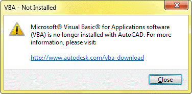
Microsoft Visual Basic for Applications software (VBA) is no longer installed with AutoCAD. For more information and free download visit: http://www.autodesk.com/vba-download
Microsoft has stopped supporting VBA for some time now & it's not ported to 64-bit.
This dialog box will show if VBA is not installed.
The sample files are now available online and are no longer included on the AutoCAD DVD. You can access the sample files at the following URL:
http://www.autodesk.com/autocad-samples
Tips & Tricks
Tips & Tricks
Commands and variables that are not well documented are:
- -EXPORT with options for setting the default translation format. (Dwf/dwfX/Pdf)
- TextEditor let you know if the text editor is open.
- CBarTransparency let you specify the transparency of constraint bars (see the CONSTRAINTBAR command).
For a free DWG viewer see AutoCAD DWG TrueView 2010. Autodesk TrueView also has DWG Convert built in so you can batch convert DWG files. You can even bind Xrefs, Purge, Set default Printer to None, Audit and fix, replace Page Setups, and place all files in a Zip file or specified directory.
Readme
Readme
Installation, Configuration and Hardware
Installation and Configuration
Note. You should close all running applications before installing AutoCAD 2010.
Installing from Dual CD/DVD ROM Drive Systems
Installation fails if you attempt to install AutoCAD 2010 by using different drives of a dual CD/DVD ROM drive system. You must use the same disc drive in order to complete the installation process.
Visual Basic for Applications (VBA)
Microsoft VBA is now made available for free download via our website at http://www.autodesk.com/vba-download. Autodesk has begun the transition from VBA technology to VSTA and .NET support. This transition will occur over several years. During this time, Autodesk will provide documentation and other assistance to help our customers and developers migrate from VBA to this new automation technology. We will continue to fully support VBA in our products, including AutoCAD 2010 and all AutoCAD 2010-based industry products. Through this free download, once VBA is installed, your existing VBA-based applications should run as in previous versions of AutoCAD.
To install the AutoCAD 2010 VBA module, download its 32-bit or 64-bit version depending on your operating system at http://www.autodesk.com/vba-download.
For 32-bit AutoCAD2010VbaEnabler32.exe
For 64-bit AutoCAD2010VbaEnabler64.exe
Close all programs.
In Windows Explorer, double-click the downloaded self-extracting EXE file.
Unzip the file to the location of your choice, or use the default location.
Follow the on-screen instructions.
HTML Help Fails When Launched from a Network Drive
You cannot launch the Help System from a network drive. A "Page Cannot Be Displayed" warning is displayed. This limitation is a result of the Windows Security Update #896258 from Microsoft.
DirectX Installation Using SCCM Fails
DirectX installations using Microsoft System Center Configuration Manager 2007 fail on systems running Microsoft Windows XP for 32- and 64-bit. Before installing with SCCM, download and install DirectX 2008 from your AutoCAD 2010 installation disc in one of the following directories, depending on your processor:
<MediaRoot>\x86\support\DirectX
<MediaRoot>\x64\support\DirectX
VC++ Runtime Installation using SCCM Forces Reboot
VC++ runtime installations using SCCM 2007 fail on systems running Microsoft Windows XP. Before installing with SCCM, download and install VC++ 2008 SP1 runtime from your AutoCAD 2010 installation disc in one of the following directories, depending on your processor:
<MediaRoot>\x86\support\VCRedist\2008\x86
<MediaRoot>\x64\support\VCRedist\2008\x64
REMEMBERFOLDERS System Variable
The Help topic for the REMEMBERFOLDERS system variable is inaccurate. The correct information is as follows.
Type: Integer
Saved In: Registry
Initial Value: 1
Controls the default path for the Look In or Save In option in standard file selection dialog boxes.
0 Restores the behavior of AutoCAD 2000 and previous releases. When you start AutoCAD by double-clicking an icon, if a Start In path is specified for the icon, then that path is used as the default for all standard file selection dialog boxes.
1 Specifies that the default path in each standard file selection dialog box is the last path used in that dialog box. The Start In folder specified for the AutoCAD icon is not used.
Use Group Policies to Install a Deployment
The Help topic Use Group Policies to Install a Deployment is missing information. The correct information is as follows.
With group policies, you can advertize a program by assigning a deployment to users’ computers.
In order for AutoCAD to run properly, the following software must be installed on the computer where the program is being installed:
Microsoft .NET 3.5 SP1 (available on the product disc)
Microsoft Internet Explorer version 6.0 SP1 or later (To download Microsoft Internet Explorer, visit www.microsoft.com)
Microsoft Installer Package (MSI) 4.5
Microsoft Windows Media Format 9.5 (prerequisite for 64-bit)
Macromedia Flash Player 9.0 or later (not installed by default)
Autodesk Design Review 2010 (not installed by default)
VC++ 2008 SP1 and VC++ 2005 SP1 runtimes for x86 operating systems; VC++ 2008 SP1 and VC++ 2005 SP1 runtimes for x64 operating systems (available on the product disc)
Microsoft National Language Support Downlevel APIs (available on the product disc)
Custom Folder in Deployments May Crash AutoCAD
The new AutoCAD 2010 Deployment Wizard - Select Installation Folder for Support Content dialog box allows you to specify a custom folder in which to copy support content.
In this dialog box, if you specify a folder location that permits Read Only permissions at the user level according to the Microsoft Vista User Acces Control, then AutoCAD may crash. To avoid this, ensure that you have write permission on your Microsoft Vista machine when creating your deployment with the Custom Folder option.
Single Shared Folder Option for Deployment Images
When using the Single Shared Folder option to create a deployment image, specify a folder name to avoid creating an invalid deployment image. Do not leave the folder name as “<Shared folder path>”.
Licensing
To Activate A Network License Through Autodesk.com
If your product does not include the Network License Activation Utility, you can activate your license by going to http://www.autodesk.com/register and following the on-screen instructions.
Running a Network License Manager on Microsoft Windows Vista
When starting the network version of AutoCAD 2010 on a Microsoft Windows Vista workstation, you may encounter licensing error -15 if the license manager is running on Windows Vista (FLEXlm server version 11.4.100). Do the following:
Install the latest service pack and updates for Microsoft Windows Vista.
If you continue to encounter errors, do the following:
On the Start menu (Windows Vista), click Control Panel Network and Sharing Center Manage Network Connections. Right-click Local Area Connection. Click Properties. Clear the check mark from Internet Protocol 6 (TCP/IPv6). Click OK.
FlexLM License is Created in Two Locations
The FLEXlm License Finder dialog box may not display when AutoCAD 2010 is launched for non-administrative users who are using Windows Vista 64-bit. The license server path information is stored in the HLKM\STOFTWARE\Wow6432Node path, which is not accessible to non-administrative users.
To fix this problem, replicate the license server path information stored in the above path to go to the HKLM\software\FLEXlm License Manager path.
Hardware
Graphics Card Driver Update
For the best program performance, verify and update your graphics card driver. For more information, see Graphics Card Driver Update.
Remote Access Applications
It is not recommended that you use any type of remote access application in conjunction with AutoCAD 2010 when it is configured to use hardware acceleration. Most remote access applications cannot support hardware acceleration, which can cause general display failure and instability. If you need to use remote access applications, disable hardware acceleration or use the /NOHARDWARE command line switch to start AutoCAD 2010 in Software mode.
Hardware Certification Database
To download and install the latest hardware certification XML file, visit the Hardware Certification website.
Join the Customer Involvement Program
You are invited to participate in helping guide the direction of Autodesk design software.
If you participate in the Customer Involvement Program, specific information about how you use AutoCAD is forwarded to Autodesk. This information includes what features you use the most, problems that you encounter, and other information helpful to the future direction of the product.
See the following links for more information.
Learn more about the Autodesk Customer Involvement Program: http://www.autodesk.com/cip
Read the Autodesk Privacy Statement: http://www.autodesk.com/cipprivacy
To turn the CIP on or off
On the InfoCenter toolbar, to the right of the Help button, click the drop-down arrow.
Click Customer Involvement Program.
In the Customer Involvement Program dialog box, select a level of participation.
Click OK.
General Information
Command Versioning
Starting with AutoCAD 2009, command versioning was introduced with the Action Recorder. Command versioning allows AutoCAD to track which command iteration should be used when executing an action macro, script file, or CUI command macro. As a result of this change, some commands may require the use of the ^R control sequence in the CUI command macro.
The ^R control sequence forces AutoCAD to use the newest version of the command. When the ^R control sequence is not used, the oldest version of the command is used.
For example, a CUI command macro using the FILLET command would require the use of the ^R control sequence to ensure that the macro worked in the same way as AutoCAD 2008 and prior releases. The following is an example of a CUI command macro using the ^R control sequence:
^C^C^R_fillet;u; r;0.1;
Some of the commonly used commands with CUI command macros that are affected by command version are:
CHAMFER
COLOR
EXPLODE
FILLET
LAYOUT
LENGTHEN
TRIM
If you are using AutoLISP, you can control which version of a command is used by preceeding the Command function with the InitCommandVersion function. The syntax for the InitCommandVersion function is as follows:
(InitCommandVersion <version_number>)
Where version_number controls which version of the command should be used for the preceeding command being exectuted by the Command function.
Configure a Database to Use With AutoCAD Drawings (dbConnect)
AutoCAD 2010 for 64-bit does not support Microsoft Jet 4.0 OLE DB Provider (for .MDB connectivity) and Microsoft OLE DB Provider for ODBC Drivers (for .XLS connectivity). For more information, see Substituting SQL Server for OLE DB in the Driver and Peripheral Guide.
Drawing File Format Compatibility
The native drawing file format for AutoCAD 2010 is not compatible with previous releases. AutoCAD 2010 can open drawing file formats from previous releases; however, in order to open AutoCAD 2010 files in previous releases you will need to use the SAVEAS command and save it to the appropriate format. The following table illustrates which drawing file formats to use when saving to a previous release.
| Drawing File Format | Applicable Releases |
| AutoCAD 2007 | AutoCAD 2007 AutoCAD 2008 AutoCAD 2009 |
| AutoCAD 2004 | AutoCAD 2004 AutoCAD 2005 AutoCAD 2006 |
| AutoCAD 2000 | AutoCAD 2000 AutoCAD 2000i AutoCAD 2002 |
| AutoCAD 14 | AutoCAD R14 |
API Compatibility
AutoCAD 2010 breaks binary compatibility with previous releases. Most applications will need to be recompiled and possibly changed to run correctly on AutoCAD 2010. For more information, see the ObjectARX Migration Guide.
Plot Styles Folder is Installed Inside the Plotters Folder
The path for the Plot Styles folder has been moved from a sibling level of the Plotters folder to a subdirectory in the Plotters folder.
Graphics Card Driver Update
You should verify and update your graphics card driver to optimize AutoCAD 2010. Use the following procedure to identify your current graphics card driver.
To identify your graphics card driver
Start AutoCAD 2010.
At the Command prompt, enter 3dconfig.
In the Adaptive Degradation and Performance Tuning dialog box, click View Tune Log.
Review the 3D Device section for information about your system's graphics card driver and driver version.
If you find that you do need to update your driver, visit http://www.autodesk.com/autocad-graphicscard to find a certified driver for your graphics card. If you do not find one, visit the graphics card manufacturer's website.
Note. If the graphics card manufacturer does not have an updated driver, check the system manufacturer's website. Companies such as IBM, Hewlett Packard, and Dell often supply their own system drivers.
Draw and Edit
Block Properties Table
In the Block Properties table, you cannot enter a combination of decimals and fractions. All numerical values must be either decimals or fractions.
Autoconstrained Polylines
Autoconstraining a polyline that has many points may reduce performance and cause AutoCAD to stop working.
Dimensional Constraints Change in Previous AutoCAD Version
Dimensional constraints do not behave as associative dimensions when opened in prior versions of AutoCAD. To reassociate dimensions, use the DIMREASSOCIATE command.
Rotating Horizontally or Vertically Constrained Geometry
Rotating horizontally or vertically constrained geometry may give unpredictable results.
User Interface
Display AutoCAD as in Previous Releases
AutoCAD 2010 introduces a new look and user interface that changes the way you access commands. To display AutoCAD 2010 as it was in previous releases, do the following:
On the status bar, click Workspace Switching.
From the list of workspaces, select AutoCAD Classic.
Use Workspaces to Switch AutoCAD Interfaces
Workspaces are sets of menus, toolbars, palettes, and ribbon panels that are grouped and organized to create a task-oriented drawing environment. In addition to AutoCAD Classic, the following task-based workspaces are available in AutoCAD 2010:
2D Drafting & Annotation
Displays tools specific to 2D drafting. Displays the new interface, including the ribbon and application menu.
3D Modeling
Displays tools specific to 3D modeling. Displays the new interface, including the ribbon, application menu, and Tool Palettes window.
To switch between available workspaces, do one of the following:
On the status bar, click Workspace Switching and select the desired workspace.
On the Workspaces toolbar, in the Workspaces drop-down list, select the desired workspace.
DesignCenter Online
DesignCenter Online (DC Online tab) is disabled by default in US English. You can enable it from the CAD Manager Control utility.
Constraint Bar Display
When the CONSTRAINTBAR system variable is set to Showall, constraint bars will always be displayed, even if the CONSTRAINTBARDISPLAY system variable is set to 0.
Where to Learn About AutoCAD 2010
Use the following resources to find more information about AutoCAD 2010:
New Features Workshop (Help menu)
Help system (Help menu)
Developer Help (Help menu > Additional Resources)
Autodesk User Group International (AUGI) (Help menu > Additional Resources)
Autodesk website at http://www.autodesk.com
Learning Resources Page at http://www.autodesk.com/autocad-learningpath
Tutorials at http://www.autodesk.com/autocad-tutorials
Cue Cards at http://usa.autodesk.com/adsk/servlet/item?siteID=123112&id=11527343&linkID=9240615
Product Removal
To Uninstall AutoCAD 2010 [Windows XP]
On the Start menu (Windows), click Settings Control Panel Add or Remove Programs.
Select AutoCAD 2010. Click Change/Remove.
On the Installation wizard Maintenance Mode page, click Uninstall.
On the Uninstall AutoCAD 2010 page, click Next.
Click Finish.
To Uninstall AutoCAD 2010 [Windows Vista]
On the Start menu (Windows), click Settings Control Panel Uninstall a Program.
Select AutoCAD 2010. Click Uninstall/Change.
If the User Account Control dialog box is displayed, click Continue.
On the Installation wizard Maintenance Mode page, click Uninstall.
On the Uninstall AutoCAD 2010 page, click Next.
Click Finish.
Updates & Service Packs
Updates & Service Packs
- AutoCAD 2012 Model Documentation Object Enabler (32-bit and 64-bit)
- Certified Hardware XML Database Update
- AutoCAD 2010 Update 2
- Autodesk Network License Manager IPv6 Support for Windows
- FLEXnet Licensing Side-by-Side Hotfix
- AutoCAD 2010 Update 1
- Regapp ID Cleanup Utility for AutoCAD 2010
- Scale List Cleanup Utility for AutoCAD 2010
- FLEXnet Licensing Hotfix for 64-bit Windows
- Register Today Proxy Licensing Hotfix
- Startup Error and Text Editing Hotfix
- Raster Design 2010 Hotfix for Licensing and Civil 3D Feature Update
- MeasureGeom Hotfix
- Hotfix: Korean AutoCAD 2010 Users Guide CHM – animations updated
- Share with Autodesk Seek Hotfix
Tips & Tricks
_VERNUM = "D.55.0.0 (UNICODE)"
Major version number for AutoCAD 2010 is R18.0
Version 11.5.0.5 of the FlexNet license manager that ships with AutoCAD 2010-based products is backwards compatible and will administer licenses for the Autodesk 2009-, 2008-, 2007-, 2006-, 2005-, 2004-, and 2002-based products as well as products from other vendors. The vendor daemon adskflex.exe version is 11.5.0.0.
AutoCAD is compiled using Visual Studio 2008 Service Pack 1. This is the only supported compiler for ObjectARX® 2010. As a programmer you also have to reference the new .lib files, which are now ‘18’ branded instead of ‘17’.
The compiler change should not have an effect on .NET applications, but you will need to reference the new AutoCAD managed assemblies (acmgd.dll and acdbmgd.dll).
Extended tooltip XAML files need to be updated to work with AutoCAD 2010.
YouTube Playlist: AutoCAD 2010 Demos - Take a first look at AutoCAD 2010 with AutoCAD Insider Heidi Hewett.
AutoCAD 2010 also is referred to as ACAD2010 or ACAD 2010.
Links
Links
Download trial of AutoCAD 2010 here.
HTML help online http://www.autodesk.com/autocad-help
Learning resources http://www.autodesk.com/autocad-learningpath
New Feature Workshop http://www.autodesk.com/autocad-newfeatureworkshop
Tutorials http://www.autodesk.com/autocad-tutorials
Cue Cards http://www.autodesk.com/autocad-cuecards
New Commands
New Commands:
| Command | Description |
|---|---|
| +CONSTRAINTSETTINGS | |
| +RIBBON | |
| +SAVEAS | |
| -ATTACH | |
| -PARAMETERS | |
| -PDFADJUST | |
| -PDFATTACH | |
| 3DPRINT | Sends a 3D model to a 3D printing service. |
| 3DSCALE | In a 3D view, displays the 3D Scale gizmo to aid in resizing 3D objects. |
| ACTBASEPOINT | Inserts a base point in an action macro. |
| ACTMANAGER | Manages action macro files. |
| ADJUST | . |
| ATTACH | Inserts an external reference, image, or underlay (DWF, DWFx, PDF, or DGN files) in the current drawing. |
| AUTOCONSTRAIN | Applies geometric constraints to a selection set of objects based on orientation of the objects relative to one another. |
| BACTIONBAR | Displays or hides action bars for a selection set of parameter objects. |
| BCONSTRUCTION | Converts geometry into construction geometry. |
| BCPARAMETER | Applies constraint parameters to selected objects, or converts dimensional constraints to parameter constraints. |
| BESETTINGS | Displays the Block Editor Settings dialog box. |
| BTABLE | Displays a dialog box to define variations of a block. |
| BTESTBLOCK | Displays a window within the Block Editor to test a dynamic block. |
| CLIP | Crops a selected external reference, image, viewport, or underlay (DWF, DWFx, PDF, or DGN) to a specified boundary. |
| CONSTRAINTBAR | A toolbar-like UI element that displays the available geometric constraints on an object. |
| CONSTRAINTSETTINGS | Controls the display of geometric constraints on constraint bars. |
| DELCONSTRAINT | Removes all geometric and dimensional constraints from a selection set of objects. |
| DIMCONSTRAINT | Applies dimensional constraints to selected objects or points on objects. |
EXPORTDWF |
Creates a DWF file and allows you to set individual page setup overrides on a sheet by sheet basis. |
| EXPORTDWFX | Creates a DWFx file where you can set individual page setup overrides on a sheet-by-sheet basis. |
| EXPORTPDF | Creates a PDF filewhere you can set individual page setup overrides on a sheet-by-sheet basis. |
| EXPORTSETTINGS | |
| EXPORTTOIMPRESSION | |
| GEOMCONSTRAINT | Applies or persists geometric relationships between objects or points on objects. |
| LAYERSTATESAVE | Saving a new layer state or replacing an existing layer state. |
| MEASUREGEOM | Measures the distance, radius, angle, area, and volume of selected objects or sequence of points. |
| MESH | Creates a 3D mesh primitive object such as a box, cone, cylinder, pyramid, sphere, wedge, or torus. |
| MESHCREASE | Sharpens the edges of selected mesh subobjects. |
| MESHOPTIONS | Displays the Mesh Tessellation Options dialog box, which controls default settings for converting existing objects to mesh objects. |
| MESHPRIMITIVEOPTIONS | Displays the Mesh Primitive Options dialog box, which sets the tessellation defaults for primitive mesh objects. |
| MESHREFINE | Multiplies the number of faces in selected mesh objects or faces. |
| MESHSMOOTH | Converts 3D objects such as polygon meshes, surfaces, and solids to mesh objects. |
| MESHSMOOTHLESS | Decreases the level of smoothness for mesh objects by one level. |
| MESHSMOOTHMORE | Increases the level of smoothness for mesh objects by one level. |
| MESHSPLIT | Splits a mesh face into two faces. |
| MESHUNCREASE | Removes the crease from selected mesh faces, edges, or vertices. |
| PARAMETERS | Controls the associative parameters used in the drawing. |
| PARAMETERSCLOSE | Closes the Parameters Manager palette. |
| PDFADJUST | Adjust the fade, contrast, and monochrome settings of a PDF underlay. |
| PDFATTACH | Insert a PDF file as an underlay into the current drawing. |
| PDFCLIP | Crops the display of a selected PDF underlay to a specified boundary. |
| PDFLAYERS | Controls the display of layers in a PDF underlay. |
| -QUICKPUB | Creates a DWF, DWFx, or PDF file and allows you to set individual page setup overrides on a sheet by sheet basis. |
| REVERSE | Reverses the order of vertices of the selected lines, polylines, splines, and helixes. |
| SECTIONPLANEJOG | Adds a jogged segment to a section object. |
| SECTIONPLANESETTINGS | Sets display options for the selected section plane. |
| SECTIONPLANETOBLOCK | Saves selected section planes as 2D or 3D blocks. |
| SEEK | Opens a web browser and displays the Autodesk Seek home page. |
| SHAREWITHSEEK | Uploads blocks or drawings to the Autodesk Seek website. |
| TEXTEDIT | Edits a dimensional constraint, dimension, or text object. |
| ULAYERS | Controls the display of layers in a DWF, DWFx, PDF, or DGN underlay. |
Changed Commands
Changed Commands:
| Changed Command | Description |
|---|---|
| 3DCONFIG | |
| -3DCONFIG | |
| 3DMOVE | In a 3D view, displays the 3D Move gizmo to aid in moving 3D objects a specified distance in a specified direction. |
| 3DROTATE | In a 3D view, displays the 3D Rotate gizmo to aid in revolving 3D objects around a base point. |
| ACTUSERINPUT | |
| ADCENTER | Manages and inserts content such as blocks, xrefs, and hatch patterns. |
| ALIASEDIT | |
| ALIGN | Aligns objects with other objects in 2D and 3D. |
| ARCHIVE | Packages the current sheet set files for archive. |
| -ARCHIVE | Packages the current sheet set files for archive. |
| ATTSYNC | Updates block references with new and changed attributes from a specified block definition. |
| AUTOPUBLISH | Publishes drawings to DWF, DWFx, or PDF files automatically to a specified location. |
| BACTION | |
| BATTMAN | Manages the attributes for a selected block definition. |
| BAUTHORPALETTE | |
| BEDIT | |
| -BEDIT | |
| BHATCH | |
| CHAMFER | Bevels the edges of objects. |
| COLOR | Sets the color for new objects. |
| CONVTOSOLID | Converts 3D meshes and polylines and circles with thickness to 3D solids. |
| CONVTOSURFACE | Converts objects to 3D surfaces. |
| CUI | |
| CUIEXPORT | Exports customized settings from the main CUIx file to an enterprise or partial CUIx file. |
| CUIIMPORT | Imports customized settings from an enterprise or partial CUIx file to the main CUIx file. |
| CUILOAD | Loads a CUIx file. |
| CUIUNLOAD | Unloads a CUIx file. |
| DGNADJUST | Adjust the fade, contrast, and monochrome settings of a DGN underlay. |
| -DGNADJUST | Adjust the fade, contrast, and monochrome settings of a DGN underlay. |
| DGNATTACH | |
| DGNCLIP | |
| DGNLAYERS | |
| 'DSETTINGS | |
| DWFADJUST | |
| -DWFADJUST | |
| DWFATTACH | Insert a DWF or DWFx file as an underlay into the current drawing. |
| -DWFATTACH | |
| DWFCLIP | |
| DWFFORMAT | Sets the default format to DFW or DWFx for the PUBLISH, 3DDWF, EXPORT, EXPORTDWF, AND EXPORTDWFX commands. |
| DWFLAYERS | |
| DXFOUT | |
| EATTEDIT | Edits attributes in a block reference. |
| EDGESURF | Creates a mesh between four contiguous edges or curves. |
| ETRANSMIT | Packages a set of files for Internet transmission. |
| -ETRANSMIT | Packages a set of files for Internet transmission. |
| EXPLODE | Breaks a compound object into its component objects. |
| EXTERNALREFERENCES | Opens the External References palette. |
| EXTRUDE | Extends the dimensions of a 2D object or 3D face into 3D space. |
| FILLET | Rounds and fillets the edges of objects. |
| FIND | |
| FLATSHOT | Creates a 2D representation of all 3D objects based on the current view. |
| -HATCH | |
| -HATCHEDIT | |
| IMAGEFRAME | Controls whether image frames are displayed and plotted. |
| IMPRINT | Imprints 2D geometry on a 3D solid or surface, creating additional edges on planar faces. |
| INTERFERE | Creates a temporary 3D solid from the interferences between two sets of selected 3D solids. |
| -INTERFERE | Creates a temporary 3D solid from the interferences between two sets of selected 3D solids. |
| INTERSECT | Creates a 3D solid, surface, or 2D region from overlapping solids, surfaces, or regions. |
| '-LAYER | |
| LIST | Displays property data for selected objects. |
| MARKUP | Opens the Markup Set Manager. |
| NAVSWHEEL | Displays a wheel that contains a collection of view navigation tools. |
| NAVVCUBE | Controls the visibility and display properties of the ViewCube tool. |
| OPEN | Opens an existing drawing file. |
| OPENDWFMARKUP | |
| OPTIONS | Customizes the program settings. |
| +OPTIONS | |
| PRESSPULL | Presses or pulls bounded areas. |
| PUBLISH | Publishes drawings to DWF, DWFx, and PDF files, or to plotters. |
| -PUBLISH | Publishes drawings to DWF, DWFx, and PDF files, or to plotters. |
| +PUBLISH | |
| PURGE | Removes unused items, such as block definitions and layers, from the drawing. |
| -PURGE | |
| QSAVE | Saves the current drawing using the file format specified in the Options dialog box. |
| QUICKCUI | |
| REFCLOSE | Saves back or discards changes made during in-place editing of a reference (an xref or a block). |
| REFEDIT | Edits a block or an xref directly within the current drawing. |
| REFSET | Adds or removes objects from a working set during in-place editing of a reference (an xref or a block). |
| REVSURF | Creates a mesh by revolving a profile about an axis. |
| RULESURF | Creates a mesh that represents the surface between two lines or curves. |
| SAVE | Saves the drawing under the current file name or a specified name. |
| SAVEAS | Saves a copy of the current drawing under a new file name. |
| SECTION | Uses the intersection of a plane and solids, surfaces, or mesh to create a region. |
| SECTIONPLANE | Creates a section object that acts as a cutting plane through 3D objects. |
| SLICE | Creates new 3D solids and surfaces by slicing, or dividing, existing objects. |
| SOLIDEDIT | Edits faces and edges of 3D solid objects. |
| STLOUT | Stores solids in an ASCII or binary file. |
| SUBTRACT | Combines selected 3D solids, surfaces, or 2D regions by subtraction. |
| TABSURF | Creates a mesh from a line or curve that is swept along a straight path. |
| TBCONFIG | |
| THICKEN | Converts a surface into a 3D solid with a specified thickness. |
| TRANSPARENCY | Controls whether background pixels in an image are transparent or opaque. |
| UNION | Combines selected 3D solids, surfaces, or 2D regions by addition. |
| VBAIDE | |
| VBALOAD | |
| -VBALOAD | |
| VBAMAN | |
| VBARUN | |
| -VBARUN | |
| VBASTMT | |
| VBAUNLOAD | |
| XATTACH | Removed ability to attach multiple drawings at a time. |
| XCLIP | Crops the display of a selected external reference or block reference to a specified boundary. |
| XEDGES | Creates wireframe geometry from the edges of a 3D solid, surface, mesh, region, or subobject. |
| XOPEN | Opens a selected drawing reference (xref) in a new window. |
Removed or Obsolete Commands
Removed or Obsolete Commands:
BORROWLICENSE
JOGSECTION
New System Variables
New System Variables:
| System Variable | Description |
|---|---|
| AECEIPINPROGRESS | |
| APPFRAMERESOURCES | |
| AUTOMATICPUB | Controls whether electronic files (DWF/PDF) are created automatically when you save or close drawing (DWG) files. |
| BACTIONBARMODE | Indicates whether the action bars or the legacy action objects are displayed in the Block Editor. |
| BCONSTATUSMODE | Turns the constraint display status on and off and controls the shading of objects based on their constraint level. |
| BLOCKTESTWINDOW | Indicates whether or not a test block window is current. |
| BPTEXTHORIZONTAL | Forces the text displayed for action parametes and constraint parameters in the Block Editor to be horizontal. |
| CBARTRANSPARENCY | |
| CCONSTRAINTFORM | Controls whether annotational or dynamic constraints are applied to objects. |
| CONSTRAINTBARDISPLAY | Displays constraint bars for objects after you manually apply a constraint or autoconstrain them. |
| CONSTRAINTBARMODE | Controls the display of geometrical constraints on constraint bars. |
| CONSTRAINTNAMEFORMAT | Controls the text format for dimensional constraints. |
| CONSTRAINTRELAX | Indicates whether constraints are enforced or relaxed when editing an object. |
| CONSTRAINTSOLVEMODE | Controls constraint behavior when applying or editing constraints. |
| DEFAULTGIZMO | Sets the 3D Move, 3D Rotate, or 3D Scale gizmo as the default during subobject selection. |
| DIMCONSTRAINTICON | Displays the lock icon next to the text for dimensional constraints. |
| DIMTXTDIRECTION | Specifies the reading direction of the dimension text. |
| DIVMESHBOXHEIGHT | Sets the number of subdivisions for the height of a mesh box along the Z axis. |
| DIVMESHBOXLENGTH | Sets the number of subdivisions for the length of a mesh box along the X axis. |
| DIVMESHBOXWIDTH | Sets the number of subdivisions for the width of a mesh box along the Y axis. |
| DIVMESHCONEAXIS | Sets the number of subdivisions around the perimeter of the mesh cone base. |
| DIVMESHCONEBASE | Sets the number of subdivisions between the perimeter and the center point of the mesh cone base. |
| DIVMESHCONEHEIGHT | Sets the number of subdivisions between the base and the point or top of the mesh cone. |
| DIVMESHCYLAXIS | Sets the number of subdivisions around the perimeter of the mesh cylinder base. |
| DIVMESHCYLBASE | Sets the number of subdivisions around the perimeter of the mesh cylinder base. |
| DIVMESHCYLHEIGHT | Sets the number of subdivisions between the base and the top of the mesh cylinder. |
| DIVMESHPYRBASE | Sets the number of radial subdivisions between the center of the mesh pyramid base and its perimeter. |
| DIVMESHPYRHEIGHT | Sets the number of subdivisions between the base and the top of the mesh pyramid. |
| DIVMESHPYRLENGTH | Sets the number of subdivisions along each dimension of a mesh pyramid base. |
| DIVMESHSPHEREAXIS | Sets the number of radial subdivisions around the axis endpoint of the mesh sphere. |
| DIVMESHSPHEREHEIGHT | Sets the number of subdivisions between the two axis endpoints of the mesh sphere. |
| DIVMESHTORUSPATH | Sets the number of subdivisions in the path that is swept by the profile of a mesh torus. |
| DIVMESHTORUSECTION | Sets the number of subdivisions in the profile that sweeps the path of a mesh torus. |
| DIVMESHWEDGEBASE | Sets the number of subdivisions between the midpoint of the perimeter of triangular dimension of the mesh wedge. |
| DIVMESHWEDGEHEIGHT | Sets the number of subdivisions for the height of the mesh wedge along the Z axis. |
| DIVMESHWEDGELENGTH | Sets the number of subdivisions for the length of a mesh wedge along the X axis. |
| DIVMESHWEDGESLOPE | Sets the number of subdivisions in the slope that extends from the apex of the wedge to the edge of the base. |
| DIVMESHWEDGEWIDTH | Sets the number of subdivisions for the width of the mesh wedge along the Y axis. |
| DYNCONSTRAINTDISPLAY | Displays or hides dynamic constraints. |
| EXPORTEPLOTFORMAT | |
| EXPORTMODELSPACE | |
| EXPORTPAGESETUP | |
| EXPORTPAPERSPACE | |
| FACETERDEVNORMAL | Sets the maximum angle between the surface normal and contiguous mesh faces. |
| FACTERDEVSURFACE | Sets how closely the converted mesh object adheres to the original shape of the solid or surface. |
| FACTERGRIDRATIO | Sets the maximum aspect ratio for the mesh subdivisions that are created for solids and surfaces converted to mesh. |
| FACTERMAXGRID | Sets the maximum number of U and V grid lines for solids and surfaces converted to mesh. |
| FACTERMESHTYPE | Sets the type of mesh to be created. |
| FACTERMINUGRID | Sets the minimum number of U grid lines for solids and surfaces that are converted to mesh. |
| FACTERMINVGRID | Sets the minimum number of V grid lines for solids and surfaces that are converted to mesh. |
| FACTERPRIMITIVEMODE | Specifies whether smoothness settings for objects that are converted to mesh are derived from the Mesh Tessellation Options or the Mesh Primitive Options dialog box. |
| FACTERSMOOTHLEV | Sets the default level of smoothness for objects that are converted to mesh. |
| FRAME | Turns the display of frames on and off for all external references, images, and DWF, DWFx, PDF, and DGN underlays. |
| GRIPSUBOBJMODE | Sets whether edge, face, or vertex grips are active upon initial selection. |
| IMAGEFRAME | Controls whether image frames are displayed and plotted. |
| LARGEOBJECTSUPPORT | Controls large object size limit support when you open and save drawings. |
| MESHTYPE | Controls the type of mesh that is created by REVSURF, TABSURF, RULESURF and EDGESURF. |
| MTEXTCOLUMN | Sets the default column setting for an mtext object. |
| PARAMETERCOPYMODE | Controls how constraints and referenced variables are copied when replicating constrained geometry. |
| PARAMETERSSTATUS | Indicates whether the Parameters Manager palette is displayed or hidden. |
| PDFFRAME | Determines whether the PDF underlay frame is visible. |
| PDFOSNAP | Determines whether object snapping is active for geometry in PDF underlays that are attached to the drawing. |
| PLINECONVERTMODE | Specifies the fit method used in converting splines to polylines. |
| RIBBONCONTEXTSELECT | Controls how ribbon contextual tabs are displayed when you single- or double-click an object. |
| RIBBONCONTEXTSELLIM | Suppresses the display of ribbon contextual tabs when the selection set includes more than the specified number of objects. |
| RIBBONDOCKEDHEIGHT | Determines whether the docked ribbon is set to the height of the current tab or a predetermined height. |
| RIBBONSELECTMODE | Determines whether a pickfirst selection set remains selected after a ribbon contextual tab is invoked and the command is completed. |
| SMOOTHMESHCONVERT | Sets whether mesh objects that you convert to 3D solids or surfaces are smoothed or faceted, and whether their faces are merged. |
| SMOOTHMESHGRID | Sets the maximum level of smoothness at which the underlying mesh facet grid is displayed on 3D mesh objects. |
| SMOOTHMESHMAXFACE | Sets the maximum number of faces permitted for mesh objects. |
| SMOOTHMESHMAXLEV | Sets the maximum smoothness level for mesh objects. |
| SUBOBJSELECTIONMODE | Filters whether a face, edge, or vertex is selected with Ctrl+click. |
| UOSNAP | Determines whether object snapping is active for geometry in DWF, DWFx, PDF, and DGN underlays that are attached to the drawing. |
| VPROTATEASSOC | Controls whether the view within a viewport is rotated with the viewport when the viewport is rotated. |
| XDWGFADECTL | Controls the dimming for all DWG xref objects. |
Changed System Variables
Changed System Variables:
| Changed System Variable | Description |
|---|---|
| DBLCLKEDIT | Controls the double click editing behavior in the drawing area. |
| DELOBJ | Controls whether geometry used to create 3D objects is retained or deleted. |
| DIMTAD | Controls the vertical position of text in relation to the dimension line. |
| ENTERPRISEMENU | Stores the enterprise customization file name (if defined), including the path for the file name. |
| IMAGEFRAME | Controls whether image frames are displayed and plotted. |
| ISOLINES | Specifies the number of contour lines per surface on objects. |
| MBUTTONPAN | Controls the behavior of the third button or wheel on the pointing device. |
| MENUNAME | Stores the customization file name, including the path for the file name. |
| NAVVCUBESIZE | Specifies the size of the ViewCube tool. |
| PUBLISHALLSHEETS | Specifies whether to load the contents of the active document or of all open documents in the Publish dialog box. |
| REFEDITNAME | Displays the name of the reference being edited. |
| XFADECTL | Controls the fading intensity percentage for references being edited in-place. |
| XREFNOTIFY | Controls the notification for updated or missing xrefs. |
Removed or Obsolete System Variables
Removed or Obsolete System Variables:
CBARDISPLAYMODE
CDYNDISPLAYMODE
CNAMEFORMAT
More
Below some early public expectations of AutoCAD 2010
New and enhanced 3D functionality is to expect. Ref.
Parametrics. Ref.
Bug fixes are always expected.
Subscription Bonus Packs for AutoCAD 2009 are expected to be included as core functions in AutoCAD 2010 so you may see the following.
The MEASUREGEOM command enables you to measure the distance, radius, angle, area, or volume of a selected object or a sequence of points. It performs many of the same calculations as the AREA, DISTANCE, and MASSPROP commands.
The REVERSE command enables you to reverse the order of vertices in selected lines, polylines, splines, and helixes.
The PEDIT command has been updated to include a new Reverse option enabling you to reverse the order of vertices in the selected polyline.
The VPROTATEASSOC variable enables you to automatically rotate a view within a layout viewport by rotating layout viewport itself. When VPROTATEASSOC is set to 1 (the default) the view will rotate maintaining its orientation with relation to the viewport. When it is set to 0, the view within the viewport will not rotate even though the viewport itself does rotate.
The PEDIT command has been updated to allow the selection of a Spline object and automatically convert it to a Polyline object.
The SPLINEDIT command has been updated to include an option to Convert to Polyline.
The new PLINECONVERTMODE variable enables you to control the fit method used in converting splines to polylines. When PLINECONVERTMODE is set to 1 (the default), polylines are created with arc segments. When it is set to 0, polylines are created with linear segments.
The PURGE (and –PURGE) command has been updated to include an option to remove zero-length geometry and empty text objects (including mtext containing only spaces).
The DELOBJ variable has been updated to support the PEDIT and SPLINEDIT commands. When DELOBJ is set to 0, the defining spline is retained. When set to any other value, it is deleted.
PDF Underlays
Now you can import PDF files, attaching them as PDF underlays. Once you attach a PDF underlay, you can use a variety of tools to snap to lines and objects, control the display of layers, move, scale, rotate, and clip the PDF underlay.
PDF Output
Key improvements have been made for publishing PDF files. File sizes have been reduced, making it easier to share designs. TrueType font support has been added, giving you control over precisely how your fonts are displayed.
New commands PDFATTACH and -PDFATTACH, PDFLAYERS, PDFADJUST and -PDFADJUST, PDFCLIP
New system variables PDFFRAME, PDFOSNAP
Subscription Bonus Pack 3 the 3D Printing Bonus Pack
The ability to prepare and print a 3D model to an online service and get back a 3D print of the model.
STL Output
STL output had been improved with updates to the existing STLOUT and EXPORT commands. Both of these methods for producing STL (stereolithography) files now enable you to select more than one solid and the model is no longer required to lie in the positive XYZ octant of the WCS.
3D Printing
The new 3DPRINT command, available on the Subscription tab of the ribbon, takes advantage of the improvements to STL output as well as providing you with easy access to 3D Printing support and services. After creating the STL file, AutoCAD automatically launches a browser window where you can request a quote from one of the featured 3D Printing Service Providers.
I hope XCLIPFRAME adds 2 to support that the frame is visible but does not plot.
Here are other things I hope to be included and fixed.
The AUGI AutoCAD Wish List usually indicates what might be included in a coming product. Here is what was presented at AU 2008.
- Convert PDF to DWG
- Solid Hatch Opacity Setting
- Design File Locking
- Import PDF into DWG or DXF (DONE and in the AutoCAD Subscription Bonus Pack 2)
- Lock Viewport scale While allowing panning
- Send all Hatches to Back
- Compare two drawings
- Block Manager
- Improve PLINE edit Tool
- Freeze in All Viewports except current
References
Techworld interview with AutoCAD product line manager Eric Stover.
![]()