
Tips when changing license server
Upgrade Autodesk Network License Manager within minutes
Silent installation of Autodesk migration tools
- If you want to create toolbar button images using BMP-files that look great you need to know that the shade of gray that AutoCAD recognizes as a transparent background is 192,192,192. This applies from Release 13 to up to at least AutoCAD 2009.
- Do you need a freeware viewer for DWG files in 2004 format now that Autodesk doesn't have a free alternative to Volo View Express? Here are two alternatives. I prefer the first one though.
Free DWG Viewer powered by Brava
Bentley View
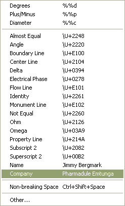
- Example how to add personal mtext symbols like below. Go here
- TrueType® text objects are filled in plot preview but not in plotted output
http://support.autodesk.com/getdoc.asp?id=TS67821 - Recover damaged drawing when RECOVER command is not successful
http://support.autodesk.com/getdoc.asp?id=TS19369 - Recover damaged drawing files
http://support.autodesk.com/getdoc.asp?id=TS67106
http://www.cvis.com/NK/NK_After%20the%20Crash.htm - You want to select a solid hatch and have a hard time to select it. If the hatch is rectangular try to select on an imaginary line going from the lower right corner to the upper left corner. You can also try using select crossing. Another way is to click on the boundary of the hatch and use CTRL to cycle between the objects and make sure you select the correct object.
- 3DCONFIG has a hidden option that is not documented. Try enter V and you will see this:
Command: 3DCONFIG Configure: 3DCONFIG
Enter option [Adaptive degradation/Dynamic tessellation/Render
options/Geometry/acceLeration/eXit] <Adaptive degradation>: V
Configure: adVanced
Enter option [Redraw on window expose/Cache viewport draw geometry/Display
lists/Fast hidden line only/Pixel Deviation/eXit] - Undocumented commands are +CUSTOMIZE, +DSETTINGS, +OPTIONS, +UCSMAN, and +VPORTS. With the '+' sign before the command name AutoCAD ask you to enter the index for the tab that will be active in the dialog box. +PUBLISH is another one.
- The undocumented SPACESWITCH system variable can be used to allow or forbid switching between paper space and model space within a layout viewport (floating modelspace) with a double click.
- The MILLISECS system variable, which is undocumented and unsupported, can be used to get the number of milliseconds since the computer was started. Available in AutoCAD since version 2002. Can be useful to track small amounts of time between two points in time.
- FNSPLITL (File Name Split To List) is an undocumented lisp function. It returns a list of (path filename extension). Example: (cadr (fnsplitl (getvar "dwgname")))
- The option RESFIT in commands like FILLET when asked to select an edge of a 3D solid. RESFIT is short for "resolution fit." ACIS uses it as the fit tolerance value when approximating curves and surfaces.
- What is QAFLAGS?
QAFLAGS been used a long time (<r12) by developers and autodesk themself too.
QAFLAGS acceps a value between 0 and 32767
bit 0 (1) : ^C in menu macro cancels grips (acts like keyboard <Esc>).
bit 1 (2) : no pause during text screen listings.
bit 2 (4) : no "alert" dialogs (text display instead).
bit 7 (128) : accepts "screen picks" (point lists) via (command) function.Normally QAFLAGS should be set to 0. Because it might be set to other values it is a good idea to put (setvar "QAFLAGS" 0) in acaddoc.lsp or any other of your lisp files that you use for startup.
When exploding multiple objects you can set QAFLAGS to 1 as in this AutoLISP example:
(setvar "qaflags" 1)
(command "._explode" (ssget) "")
(setvar "qaflags" 0)
- Q: I have problems binding xrefs.
A: Ideas how to resolve problems with binding xrefs.
If you have nested xrefs that are unloaded you cannot bind them. The solution is either to detach them where they are attached or to change them from attach to overlay.
Try to PURGE both the drawing with the xrefs and each xref.
If there are nested xrefs unloaded you have to either detach them or set them to overlay
Try to bind the xrefs one by one and close and open the xref dialog box for each time and find if there is a specific drawing you cannot bind.
If you find one or more xrefs that are not bound try to attach them one by one into a new empty drawing. Now try to bind. This can give you a hint of where the problem resides.
If the xref contains proxy objects there might be an "Invalid" message. To resolve the problem try to find an object enabler. To have a hint of if there are proxy objects and what application have created them set the system variable PROXYNOTICE to 1 and reopen the drawing. If a notice of proxy objects are displayed try to find the missing application. AecArchBase is for example Architectural Desktop. Be sure that the Show Proxy Objects option is selected on the Open and Save tab in the Options dialog box. If you are allowed to (since this destroys intelligence and maybe some geometry), you can saveas DXFr12, close the drawing, open it again and then save as DWG2000-format. This might even be necessary to be repeated twice. Try wblocking everything into a new drawing and attaching it instead of the old. You can use QSELECT to find proxy objects. Look for the Object type: ACAD_PROXY_ENTITY. Observe that if they are nested in blocks you have to explode all blocks one or many times to find it.
Try to recover and audit both the drawing and the xref file.
Check if there is a block in the xref file with the same name as the xref itself. If so rename one of them.
It might be possible for the one creating the xref file and having the custom application to explode the objects into plain AutoCAD objects.
To detach an xref that exists in multiple layouts: In each layout, erase the object representation of the xref you want to detach. From the Insert menu, choose Xref Manager. In the Xref Manager, detach the xref.
There might be blocks with no name.
If you are unable to detach multiple references. This error can occur when you try to detach an xref that is used in multiple layouts. For example, you might have referenced the same title block into multiple layouts. Make sure that you have purged the drawing as well.
Try do detach, attach and bind.
Try this on another PC. Sometimes a reboot has helped.
If nothing else is working detach the xref and insert it with INSERT command. But first check the inserting point, scale, rotation, layer, if it's clipped and so on.
Look if you have blocks with invalid names like "70/50/30" in the xref you cannot bind. <>/\":?|,=` are invalid characters in block names.
Recover and Audit drawings that are damaged
The first two options to fix a drawing is to use the RECOVER and AUDIT commands in AutoCAD. Here are some other options:
- Using Windows Explorer or the Windows Find feature, search the entire hard disk for SV$ files or BAK files with the same name as the drawing. Rename those files so that they have a DWG extension, and you may be able to open them.
- Use the DDINSERT command to insert the corrupt drawing into a new drawing. Note: Be sure when inserting the drawing that you do not select 0,0 as the insertion point. Select an arbitrary point on the screen, or if the coordinates are important, enter 1,1. You can move the drawing back to 0,0 later when the file has been recovered completely.
- Start a new drawing using the Start from Scratch option.
- Open the drawing in a previous release of the software, if available.
- Export the drawing as a DXF™ file, then import the DXF file.
- If the drawing was last saved in the AutoCAD 2000 or 2004 format, you can try using partial open to load the drawing one layer at a time until you find a layer containing an error and then skip that layer next time. See related documents for instructions on using the partial open feature.
From Without a Net: First, open a blank DWG and run the RECOVER command. You can then browse to the problematic file, and AutoCAD will attempt to repair any errors it finds. Save the file, and then see if everything works as you expect it to. If not, continue on to the steps below:
1) Open the problematic file and make sure all layers are on and thawed.
2) Detach any XREF's.
3) Type in -PURGE at the command line (remember to enter the dash before the command). Type R for RegApps. Delete all RegApps in the file. It is not necessary to do them one by one because sometimes there can be thousands and it would take a very long time.
4) Type AUDIT, and select Y for yes to audit the file of any errors.
5) Type PURGE and purge the file of anything that can be purged.
6) Using the WBLOCK command, block out all the information in the file to create a new drawing. Select the objects by windowing them; do not just type ALL.
7) Open a blank DWG. Do not use any templates. (Set the STARTUP variable to 0, and then open a file if you are unsure if you are using templates)
8) Using the INSERT command, insert the file created in step 6.
9) EXPLODE the newly inserted information so it is not a block any longer.
10) Test to see if the file now works correctly. If it does, you can start to add in the Xref's again one by one. Test the file after each insertion. If the problem returns after inserting an Xref, you'll know that that file needs to be cleaned using these steps as well.
As a final note, I highly recommend running the AUDIT and PURGE commands before each save. This will keep the file clean and greatly reduce the chance of any corruption setting in.
- Q: How can I plot with previous plot settings from the command line to use in scripts or in a LISP program?
A: (command "-plot" "no" "" "previous plot" "" "" "" "")
- Q: How can I plot by code and set it to plot more than 1 copy?
A: Following work to plot 3 copies using the previous plot setting from the command line:
(progn
(command "-plot" "no" "" "previous plot" "" "" "Y" "N")
(setq plotnr 3)
(setq ad (vla-get-activedocument (vlax-get-acad-object)))
(setq plot (vla-get-plot ad))
(vla-put-NumberOfCopies plot plotnr)
(vla-PlotToDevice plot)
)
Notice that you can't change the setting in the plot dialog box. If you want
to do that you have to do it from outside AutoCAD like this.
1) Start an external application like (startapp "f:\\SetPlotNo.exe"), could
be done with VB as follow.
2) Make sure that the active tab of the plot dialog box is the first one,
could be done setting the following registry to 0,
HKEY_CURRENT_USER\Software\Autodesk\AutoCAD\R15.0\
ACAD-1:409\Profiles\AutoCAD 2002\PlotSettingActiveTab
3) Open the dialog box by using SendKeys to AutoCAD.
...
AppActivate AcadApp.Caption
SendKeys "PLOT ", True
SendKeys "%b ", True
' No of copies
SendKeys "3", True
...
This might give you some ideas...
- Q: I want to show the plot dialog box using lisp. How do I do?
A: This will work: (initdia) (command "._plot")
- Q: I want want to easy copy links/queries/labels created with dbConnect from one drawing to another.
A1: Create an empty drawing with only the links/queries/labels you want, let's say you call it dbTemplate.dwg. To easily have them into an existing drawing you only have to insert dbTemplate.dwg and explode it and there you go. This could easily be done on a button. Observe * before the drawing name makes it explode. -insert *dbTemplate.dwg 0,0 1 0
A2: Open dbConnect Manager with CTRL+6. Drag and drop the links/queries/labels from one drawing to another. - Q: The labels disappears after I reloaded them. Where are they?
A: You have probable used a wrong field as key. It has to be a field that is unique.
- Q: My silent install doesn't continue to the end.
A: Check the C:\WinNT\AcadDeploy.log (or in C:\Windows) file that might give you some hint of what has happened. One reason might be that there is no place left for the installation. You can also try to run the following file that you'll find in you share installation folder. \IMAGE\client.exe
FlexLM / FlexNet
- Q: How can I easily distribute environment variables to set LM_LICENSE_FILE?
A: Create a registry file named license.reg looking like below where EMTNT04 and ARNNT02 are the names of two servers, change to fit yours or you can use the IP address. Sometimes it can be good to add port number too in the format port@server.
REGEDIT4
[HKEY_LOCAL_MACHINE\System\CurrentControlSet\Control\Session Manager\Environment]
"LM_LICENSE_FILE"="@EMTNT04;@ARNNT02"
This can then be called in a command file like this:
regedit /s \\servername\sharename\license.reg
See more about this on the Autodesk Network License Manager Page
- Q: Is it possible to use version 8.3c (or newer) of FlexLM?
A: Yes, we use it without any problems. Running both AutoCAD 2002 and AutoCAD 2004 has worked well.
- Q: How can I check the status from a client PC?
A: have an cmd-file on client machines so it's possible to check the license status without doing it on the license server. Example below, where arnnt04 is the name of the server. The path to lmutil must be changed to work for you.
@echo off
"M:\CAD\LMTOOLS\cmd\lmutil" lmstat -a -c 27000@arnnt04<br< a="">> pause
- Example on how the adskflex.opt file can look like:
REPORTLOG +d:\flexlm\license\report.rl
# If the application is idle for 900 seconds
# the server reclaims the license.
TIMEOUT 42600ACD_2004_0F 900
TIMEOUT 43200ARCHDESK_2004_0F 900
TIMEOUT 46300ACD_2005_0F 900
TIMEOUT 46700ARCHDESK_2005_0F 900
# This line defines the Group "ADTUSER",
#add or remove login names here.
GROUP ADTUSER user1 user2 user3
GROUP ACADUSER user1 user4 user5 user6
GROUP ADTEXCLUDE user4
# This line will reserve 1 licens for the group "ADTUSER"
RESERVE 1 43200ARCHDESK_2004_0F GROUP ADTUSER
# This line will exlude user4 from using ADT
EXCLUDE 43200ARCHDESK_2004_0F GROUP ADTEXCLUDE
# This line will allow maximum 2 licenses
#for the group "ACADUSER"
MAX 2 42600ACD_2004_0F GROUP ADTUSER
- Q: Tips on ceiling grids?
A: Ceilings don't need to be drawn in the base plan, you can do them in xrefs even on small projects. A great way to make frids is to go to a reflected display & use Bpoly to create ceiling boundaries, then convert to
ceiling grids.
- Q: How can I change the title bar to say AutoCAD instead of Architectural Desktop?
A: Have a look here to download the code.
AutoCAD Command and System Variable Map
To download PDF version (90Kb) http://betaprograms.autodesk.com/files/commandmap-draft.PDF
ADC - AutoCAD Design Center
Do you miss preview images/icons of blocks? Use the command BLOCKICON. It generates preview images for blocks created with Release 14 or earlier and even A2k.
You can get ADC to navigate to a specific folder, drawing or even custom contents like layouts.
You can start ADC like these examples, (can be placed in a custom menu for easy access):
(command "._adcnavigate" "r:/cad/r15g/blocks/")
(command "._adcnavigate" "r:/cad/r15g/blocks/template.dwg/")
(command "._adcnavigate" "r:/cad/r15g/blocks/template.dwg/layouts")
;;; Navigate to current drawings path
(command "._adcnavigate" (getvar "dwgprefix"))
(callADC "r:/cad/r15g/blocks/" "template.dwg" "layouts")
(defun callADC (path fname custcont)
(if (/= fname "") (setq fname (strcat fname "/")))
(command "._adcnavigate" (strcat path fname custcont))
)
Arguments
path a valid existing path fname an existing dwg or dwt-file
or an emty string: ""custcont any of (blocks" "dimstyles" "layers" "layouts" "linetypes" "textstyles" "xrefs")
or an emty string: ""
Mouse
To make your work with AutoCAD more effective you should invest in a IntelliMouse compatible mouse. Personally I've been satisfied with IntelliMouse Explorer that doesn't jam like an 'ordinary' one.
The following table lists the IntelliMouse mouse actions supported in AutoCAD.
| To ... | Do this ... |
| Zoom in or out | Rotate the wheel forward to zoom in, backward to zoom out Move the mouse to the point you want to have as center when zooming. |
| Zoom to drawing extents | Double-click the wheel button |
| Pan | Press the wheel button and drag the mouse |
| Horizontal and vertical pan | Press Shift and press the wheel button and drag the mouse |
| Joystick pan | Press Ctrl and press the wheel button and drag the mouse |
| Change the zoom factor | Set the system variable ZOOMFACTOR (Default is 10%). But this makes it too slow so raise it to 50 or what you feel is comfortable. |
Did you know that you can use this functionality when in the orbit command too?
You might want to disable the scroll bars in drawing window since it might interfere with scroll-mouse.
Remember also to set MBUTTONPAN to 1.
If you have another mouse you might have to :
1) Set wheel button 2 option to "Middle"
2) Turn on "use Office 97 compatible scroll only"
3) Set the Scrolling size option to "None" if not the first two worked.
4) Do you have the latest driver?
How can I know where my drawing is inserted as an xref?
Use DesignCenter or Ctrl+2 and Find Button.
There you have the option to search for xrefs in many drawings.
There is also possible to find Blocks, Dimstyles, Drawings,Layers
Layouts, Linetypes and Textstyles.