
The newest release of AutoCAD, codenamed "Keystone" was released March 26, 2013.

This is the 28th version of AutoCAD.
Previous AutoCAD version AutoCAD 2013 and newer version AutoCAD 2015.
New and/or enhanced functions
New and/or enhanced functions
File format
The DWG file format is the same as in AutoCAD 2013: "AutoCAD 2013 Drawing". The DXF file format is also the same.
Command Line Enhancements
The command line has been enhanced to provide smarter, more efficient access to
commands and system variables. And, you can use the command line to find other content such as hatch patterns, visual styles, and internet help.
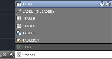
AutoCorrect
If you mistype a command, instead responding with “Unknown command”, AutoCAD autocorrects to the most relevant and valid AutoCAD command. For example, if you accidently type TABEL, the TABLE command is automatically launched.
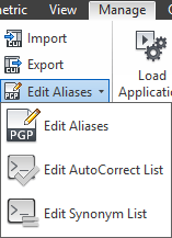
To customize the AutoCorrect List click Manage tab > Customization panel > Edit Alias (flyout) > Edit AutoCorrect List.
The autoCorrectUserDB.pgp file will be opened. The syntax is as follow:
INCORRECT, *CORRECT
For example, if you consistently mistype BLOCK as BOLCK, enter
BOLCK, *BLOCK
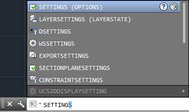
AutoComplete
AutoComplete command entry is enhanced to support mid?string search. For example, if you type SETTING on the Command line, the suggestion list displays commands containing the word SETTING anywhere within it, not just at the beginning.
Adaptive Suggestions
Commands in the suggestion list are initially displayed in the order of their usage based on general customer data. As you continue to use AutoCAD, the order of commands in the suggestion list will adapt to your own usage habits. The command usage data is stored in the profile and adapts to each user.
%appdata%\Autodesk\AutoCAD 2014\R19.1\enu\Support\AcCommandWeight.xml
Synonym Suggestions
The Command line has a built in synonym list. Enter a word at the command line and it will return a command if a match is found in the synonym list. For example, if you enter Symbol, AutoCAD finds the INSERT command so you can insert a block. Or if you enter Round, AutoCAD finds the FILLET command so you can add a fillet to a corner.
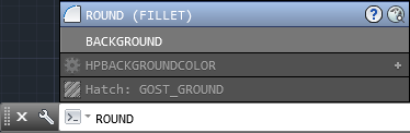
You can add your own words to the AutoCorrect and Synonym lists using the Edit Aliases tool from the Manage ribbon tab.
In the acadSynonymsGlobalDB.pgp file, enter the words in the following format:
SYNONYM, *COMMAND
For example, if want you BLOCK to be displayed in the suggestion list when you enter SYMBOL, enter
SYMBOL, *BLOCK
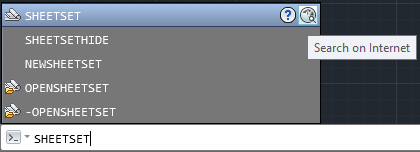
Internet Search
You can quickly search for more information on a command or system variable in the suggestion list. Move the cursor over the command or system variable in the list and choose the Help or Internet icons to search for relevant information. The term AutoCAD is automatically prepended to the current term for searching the internet.
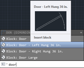
Content
You can use the command line to access layers, blocks, hatch patterns/gradients, text styles, dimension styles and visual styles. For example, if you enter Door at the command line and the current drawing has a block definition with the name Door, you can see a preview of it and quickly insert it right from the suggestion list.
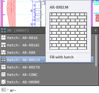
Here is what it look like for Hatch patterns.
Categories
To make the suggestion list easier to navigate, system variables and other content are organized into expandable categories. You can expand a category to see the results or press the Tab key to cycle through each category.
Input Settings
You can customize the behavior of the command line using controls in the Input Settings menu when you right?click on the command line. In addition to the previous options to enable AutoComplete and search for system variables, you can enable AutoCorrect, Search Content and Mid?string Search. All of these options are turned on by default.
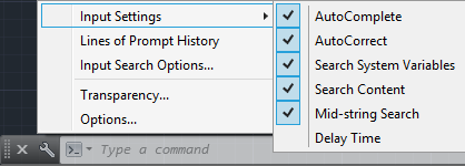
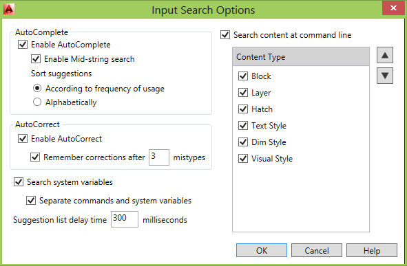
Another right?click option provides access to the new Input Search Options dialog box.
Dynamic input also supports AutoCorrect, mid?string search, AutoComplete, Synonym Suggestions and adaptive suggestions.
Binary Security
AutoCAD 2014 provides new controls to enhance software security and help prevent loading and running of unauthorized or malicious AutoLISP and VBA applications.
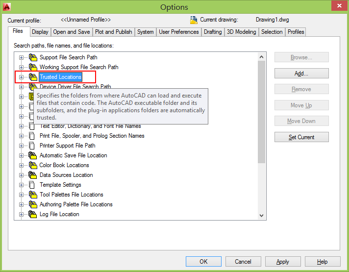
The Files tab of the Options dialog box includes Trusted File Search Path. You can also access these controls using the new TRUSTEDPATHS and TRUSTEDDOMAINS system variables.
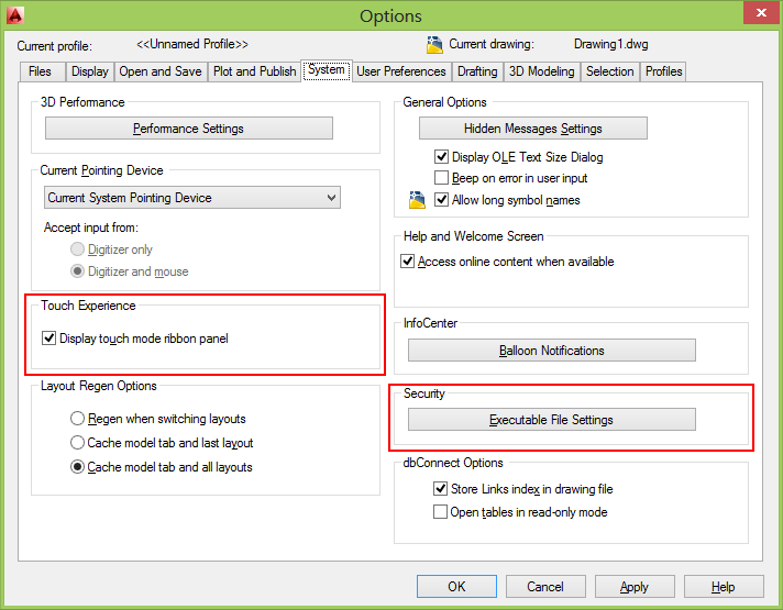
A security control on the System tab of the Options dialog box provides access to new Executable File Settings.
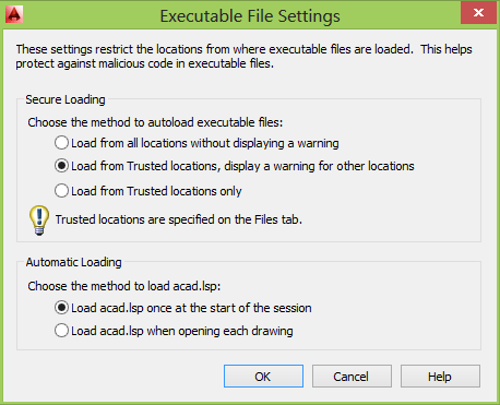
You can allow executable files to be loaded from all search paths or only from the trusted locations specified on the Files tab. And, you can choose to display a warning before loading executable files outside the trusted locations.
When Trusted Locations or TRUSTEDPATHS includes a folder that ends with \... (backslash and three dots), all of its subfolders are also trusted.
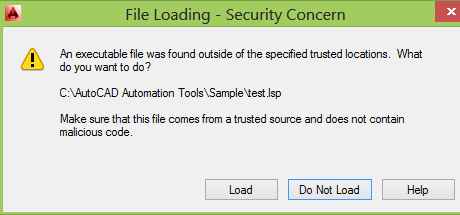
File Loading - Security Concern
An executable file was found outside of the specified trusted locations. What do you want to do? Make sure this file comes from a trusted source and does not contain malicious code.
These options are applied to the new SECURELOAD system variable.
Similar have been added to the Deployment Wizard enabling you to apply Secureload functionality to network deployments.
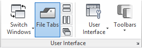
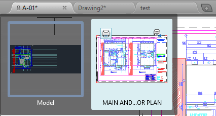
File Tabs
Drawing tabs have been added and is a fast and visual way to switch between open drawings or to create new ones. You can turn the file tabs bar on or off using the File Tabs control on the View ribbon tab.
When File Tabs are turned on, a tab for each open drawing is displayed at the top of the drawing area. File tabs are displayed in the order they were opened. You can drag and drop tabs to change their order. If there is not enough room for all the file tabs to display across the area, an overflow menu at the right end of the file tabs bar provides access to the additional files.
A lock icon on a tab indicates that the file is open as read?only and an asterisk indicates if the file has been modified since its last save.
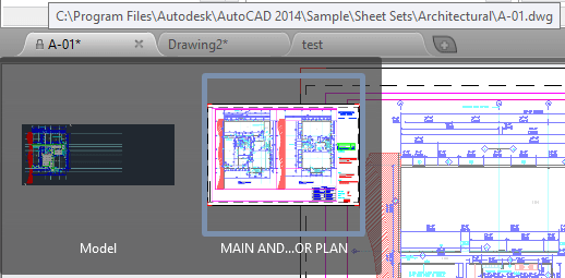
When you pass the cursor over a file tab, preview images of the model and layouts are displayed. If you pass the cursor over one of the preview images, the corresponding model or layout is temporarily displayed in the drawing area and Plot and Publish tools are accessible from the preview image.
The right?click menu for file tabs enables you to create, open, save and close files including the ability to close all open files except the one on which you right?clicked. You can also copy the full file path to the clipboard or open the file location in Windows Explorer.
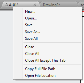
A Plus (+) icon to the right of the drawing tabs, enables you to easily create new drawings, automatically adding their tabs as they’re created.
FILETAB command displays the File tabs at the top of the drawing area.
FILETABCLOSE command hides the File tabs at the top of the drawing area.
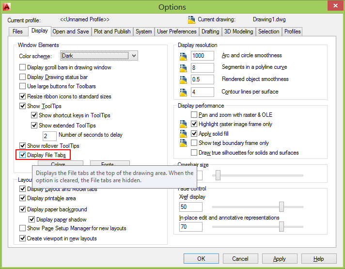
Display File Tabs is available in Options > Display.
Autodesk 360
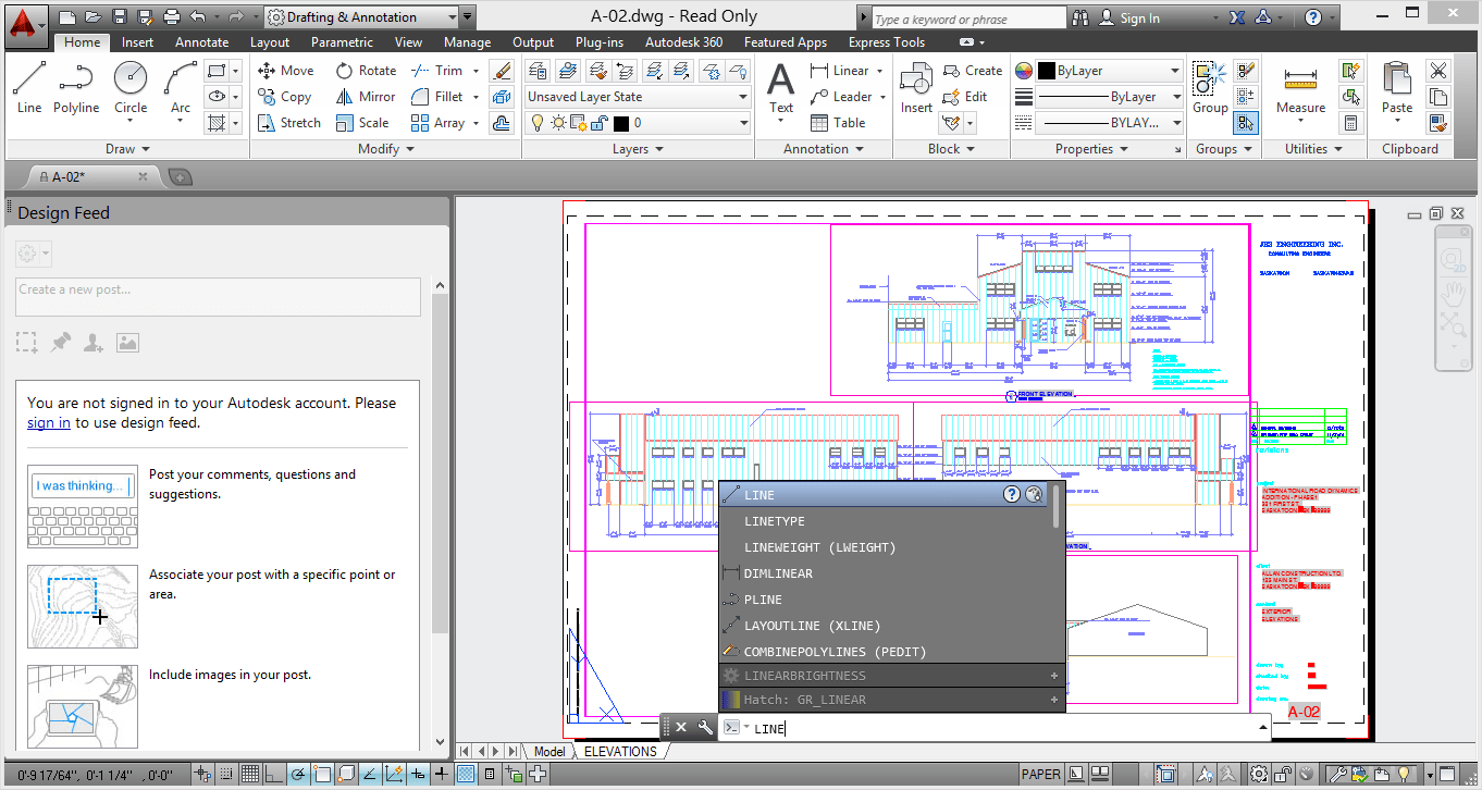
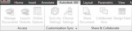
In AutoCAD 2014 the Online ribbon tab is renamed to Autodesk 360. It includes a new Open Folder tool for easy access to the Autodesk 360 folder on your local machine and the new Design Feed enables you to enter posts and images for a drawing that can be shared online.
This is what it look like if the Autodesk 360 desktop companion is not installed and the commands are unavailable.
ONLINEOPENFOLDER command opens your local Autodesk 360 folder in Windows Explorer.
Design Feed
Design Feed, accessible from the Autodesk 360 ribbon tab, displays a palette in which you can enter text messages and attach images to be shared online with colleagues, clients, and consultants through Autodesk 360.
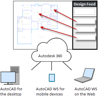
Posts appear with related drawings on the desktop, on the web, and across mobile devices. Turn on Design Feed from the Autodesk 360 ribbon tab.
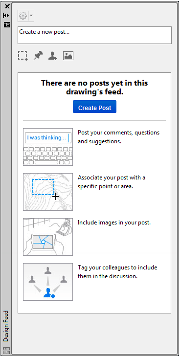
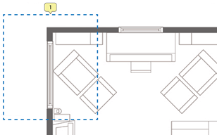
You can associate your message with a location or area within the drawing. In the example below, the first post was associated with an area and indicated with a design feed bubble. The settings button on the Design Feed palette lets you control the display of the bubbles.
You can tag colleagues, clients, and consultants to notify them of your post; notifications will be sent to them by email and will also appear within AutoCAD.
After you finish creating a post, it is saved to your Autodesk 360 account with the drawing, along with any images that you attached. Using Autodesk 360, the people that you have authorized can view the drawing and its associated posts, and the people that you have tagged can post replies. When the questions in a post and its replies are no longer active, you can resolve the thread to hide it in the Design Feed palette.
DESIGNFEEDCLOSE command closes the Design Feed palette.
DESIGNFEEDOPEN command opens the Design Feed palette.
Geolocation
Support for Geographic locations has been significantly enhanced. It includes the same Coordinate System Library as AutoCAD Map 3D and new Autodesk Live Maps.
There are many benefits to defining a location in your drawing. When you import geolocated data into a geolocated drawing, AutoCAD transforms the data based on the drawing's geographic location. You can see your design within the context of its location and if you render the model, it will have the correct sun angle. If you export the drawing to a mapping service like Google Earth, it will automatically display at the correct location. When you insert geo?referenced images or blocks into your geo?referenced drawing, they are automatically placed in the correct location and at the correct scale. For example, imagine large projects that have multiple designers working separately on the same design, such as a housing project. If each designer uses the same coordinate system, all the drawings will insert at their appropriate locations when combined into a single file. You can mark specific point of interest in your drawings knowing that those points correspond to logical geographic locations. And, if you have a GPS device enabled on your computer, you can see your current position in the drawing and you can even mark positions as you walk around. For example, landscape architects can visit the site and take notes of the surroundings by marking them on the drawing. You can set a geographic location in your drawing using the Set Location tool on the Insert ribbon tab. Choose to set the location using Autodesk Maps Service or by selecting a KML or KMZ file.
Autodesk Maps Service is automatically available from AutoCAD 2014 when you are signed into your Autodesk 360 account.
When specifying a geographic location from a map, you can search for an address or latitude and longitude. If multiple results are found, you can click on each one in the results list to view the corresponding map and you can display the map as road or aerial data.
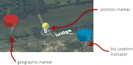
When you find the correct location, you can drop a marker to select it. A pin is placed on the map and corresponding latitude, longitude, and time zone are automatically applied. You can move the pin or modify the location properties as needed. An icon to the right of the elevation unlocks the latitude and longitude for manual editing.
Collapse the Results panel to maximize the map and easily change between Road and Aerial displays.
AutoCAD assigns World?Mercator as the default coordinate system or you can choose from a library of coordinate systems. The coordinate system defines the scale of the map.
The current drawing unit is automatically displayed in the Geographic Location dialog box or you can choose from a list of standard units. The inserted map is automatically scaled appropriately for the specified drawing units.
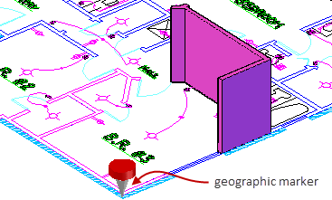
When a map is applied to a drawing it is always displayed below drawing geometry. Whether apply a geographic location using a map or by selecting a KML/KMZ file, the geolocation marker is displayed in the drawing at a point you specify and a new Geolocation tab is added to the ribbon.
The Geolocation ribbon tab includes tools for modifying the geolocation and map display. You can specify a different location using the Autodesk Map Service or by selecting a KML or KMZ file. Pick a new location and north direction to reorient the geo?marker. Or, completely remove the location data and assigned coordinate system from the drawing.
Easily switch between aerial and road map or turn off the map display while still maintaining the geographic location and coordinate system data.
If you are working on a GPS –enabled laptop, you can use the Locate Me tool to identify your current location in the map.
You can mark positions in the drawing by entering lat?long data, using your current location (for GPS enabled devices), or by picking points. For each position, you can enter text to describe the position. The new GEOMARKPOSITIONSIZE system
variable controls the initial size of the marker. You can modify the size, contents, and other properties of selected position markers using the Properties palette.
Position Marker is a new object type. When listed it shows as POSITIONMARKER. Internal name seen for example with AutoLISP is AcDbGeoPositionMarker.
(0 . "POSITIONMARKER") ... (100 . "AcDbGeoPositionMarker")
Reality Capture
Reality Capture enables you to take a 3D laser scan of an object, topography, a building or even an entire town and attach it to an AutoCAD drawing as point cloud data. You can then use it as a real?world reference for your design work. This point cloud data is stored as thousands, even millions, of points in 3D space.
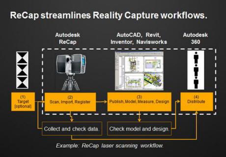
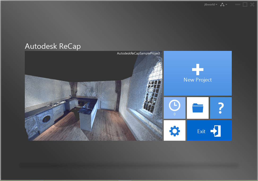
Autodesk ReCap is a separate application which enables you to create a point cloud project file (RCP) that references multiple indexed scan files (RCS). It is installed with AutoCAD 2014, by default and you can launch it from the Window’s Start menu or from the Autodesk ReCap desktop icon.
You can use Autodesk ReCap to convert scan file data to a point cloud format that can be viewed and edited in other products. Autodesk ReCap processes massive datasets enabling you to aggregate scan files and clean, section, spatially sort, compress, measure, and visualize them. The resulting high?speed formats can then be used by AutoCAD and other Autodesk applications including Revit and Autodesk Inventor.
To use Autodesk ReCap, you must log into your Autodesk 360 account. In Autodesk ReCap, you can create a new project by selecting the scan files to import.
It supports scan data files from many popular formats including Faro, Leica, and Lidar just to name a few.
After selecting scan files to import, you can adjust import settings that affect the size and appearance of the point cloud. The imported files are displayed on the project screen where you can use a variety of tools to work with scan files.
The Home tile menu provides access to a variety of project?related activities. You can save the current project as a Point Cloud Project file (RCP) or export it to a Point Cloud Scan file (RCS) both of which can be attached to AutoCAD drawings. You can import additional scan files into the current project or open a different project. A Preferences tool enables you to modify project settings and the Help tool provides detailed information about working with Autodesk ReCap.
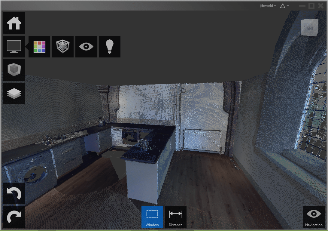
The Display Tools tile menu provides tools for analyzing the point cloud, changing its appearance, modifying the display of components in the work area, and specifying lighting options.
The Limit Box tile menu provides tools for working with limit boxes to define different volumes within the scene.
The Project Navigator tile menu provides one?stop access to scan regions and individual scan files. The Project Navigator can remain attached to the Project tile menu so that it opens only when you hover over it or work within it. If you want to keep it open as you work, detach it from the tile menu and move it to a location on or off the program work area.
After producing point cloud files Autodesk ReCap, or if you’ve received files from someone else, you can attach them to your AutoCAD drawings.
Point Cloud
Point cloud functionality is enhanced in AutoCAD 2014 to support inserting of Point Cloud Project (RCP) and Scan (RCS) files produced by Autodesk ReCap in addition to the previously supported PCG and ISD formats.
You can select point cloud files using the Attach tool from the Point Cloud panel of the Insert ribbon tab.
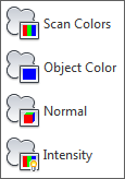
After a point cloud is attached, the contextual tab that is displayed when the point cloud is selected is enhanced to make it easier to work with point clouds. You can now change the stylization (colorization) of point clouds to colorize the point cloud based on the scan colors (colors captured by the scanner), object color (color assigned to object), Normal (colorize based on the normal direction of point) or Intensity (reflectivity value of points). If normal or intensity data was not captured with the scan, those stylizations are disabled. In addition, more clipping tools are displayed on the ribbon to make it easier to clip the point cloud.
AutoUpdate is turned off by default, preventing the point clouds from automatically updating every time the view is changed and improving performance when working with large point clouds. You can use the refresh button to manually update the point clouds.
Windows 8 touchenabled device
AutoCAD 2014 supports Windows XP, Windows 7, Windows 8 and Windows 8.1. If you are using a Windows 8 touchenabled device, you can benefit from smoother pan and zoom performance. A new control on the System tab of the Options dialog box displays a touch mode ribbon panel when a touch screen device is detected.
The Touch ribbon panel enables you cancel the current command and returns you to the Select/Command prompt.
Exchange Apps
A default installation of AutoCAD 2014 adds several valuable apps from Autodesk Exchange including the Featured Apps ribbon tab, the Exchange App Manager and the Import SKP tool that imports a sketchup file into the current drawing as a block reference.
The Feature Apps ribbon tab provides easy access to the Exchange site where you can browse and download AutoCAD apps; some for free and some for purchase. It also includes a selection of featured apps that you can select and download directly from the Featured Apps tab without browsing through the entire Exchange site.
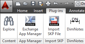
The Exchange App Manager and the Import SKP File tools are accessible from the Plug?ins ribbon tab.
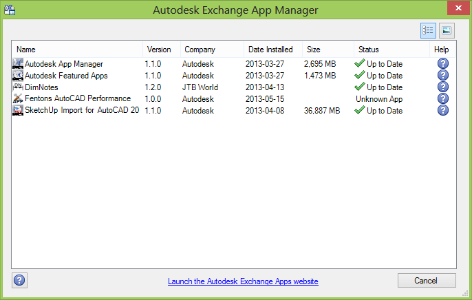
Use the Exchange Apps Manager to easily view and update installed apps. Double?click on an app or choose Help from the right?click menu to learn more about it. Just as easily uninstall or rate the app using the right?click menu options.
Xref Manager
The display of linetypes and layers from externally referenced drawings is enhanced in AutoCAD 2014. Xref linetypes are not displayed in the linetype list of the ribbon or Properties palette. Xref layers are still displayed in the ribbon so you can control their visibility but they are not displayed in the Properties palette.
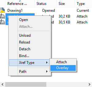
You can easily change the attachment type for an xref between Attach and Overlay by double?clicking in the Type column.
A new option in the right?click menu enables you to change the xref type for multiple selected xrefs at the same time.
The External References palette includes new tools to easily change the path of selected xrefs between Absolute and Relative. You can also remove the path completely.
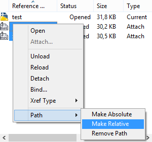
The –XREF command includes a new PATHTYPE option enabling you to automate these path changes through scripting.
Arc Creation
Easily draw an arc in either direction using by pressing the Ctrl key to switch directions as you draw.
FILLET and CHAMFER of Polylines
Now the commands fillets or chamfers the first and last segments of an open polyline to create a closed polyline.
Sheet Sets
When creating a new sheet in a sheet set the CreateDate field stored in the associated template (.dwt) displays the creation date of the new sheet rather than the creation date of the template file.
Plot Styles
The CONVERTPSTYLES command enables you to convert the current drawing to either named or colordependent plot styles. In AutoCAD 2014 it is enhanced to support style names with spaces.
Layer Manager
The number of layers displayed on the ribbon has been increased.
Layers are now displayed using natural ordered sort. For example, the following layer names 1, 4, 25, 6, 21, 2, 10 are sorted as 1, 2, 4, 6, 10, 21, 25 instead of 1, 10, 2, 25, 21, 4, 6.
A new Merge option "Merge selected layer(s) to ..." in the Layer Manager enables you to select one or more layers from the layer list and merge the objects from those layers onto a different layer. The original layers are automatically purged from the drawing.

Materials Browser
There are some enhancement in the Materials Browser.
1. List of materials: each material has it’s own background stripe.
2. Added filtering of displayed materials from a bar.
3. New, more meaningful icon for managing libraries.
4. It is possible to show/hide library panel.
5. Added icon to show/hide library tree on the bar/command removed from drop down list.
6. New interface of material tree.
7. Added sorting by category to drop down list in Document Materials.
Dimensions
The new DIMCONTINUEMODE system variable provides you with more control when creating continued and baseline dimensions. When DIMCONTINUEMODE is set to 0, the DIMCONTINUE and DIMBASELINE commands create dimensions based on the current dimension style. When set to 1, they apply the dimension style of the selected dimension.
Text
Single line text is enhanced to maintain the last justification setting until it’s changed.
Adds Left to the Justification prompt options in the TEXT command.
TEXTJUSTIFY (System Variable) displays the default justification used by the TEXT command to create single-line text. Initial value: Left. This setting is changed by the Justify option of the TEXT command.
Annotation scale in the Select Annotation Scale dialog box is set only with a drop-down list (no direct entry).
Attributes
The default behavior for inserting blocks with attributes displays the dialog box. ATTDIA is set to 1.
Hatch
The Hatch tool on the ribbon maintains the previous method for selecting objects to hatch: Pick internal point or Select objects. The Undo option is added to the command line.
HPPICKMODE (System Variable) indicates whether the default method for identifying hatch areas is clicking enclosed locations or selecting boundary objects.
Raster Images
The display of and performance with raster images seems to have been improved when working with large image files.
Hardware Acceleration
The Hardware Acceleration icon has been updated.
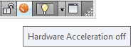
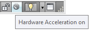
The check engine light enhancements are a stronger suggestion to keep the video card files up-to-date on your computer. If you are up-to-date you will not notice it.
If you are not updated, you will see an orange icon on the tray (stands out) to indicate no video acceleration is being used and you will get a dialog explaining how to get the newest drivers and why they are important or that no video card is being used at all.
Loading of JavaScript
WEBLOAD command loads a JavaScript file from a URL, and then executes the JavaScript code contained in the file.
If you try to load a JavaScript file from an untrusted server, one that is not specified in the TRUSTEDDOMAINS system variable, a security warning will display.
Help
AutoCAD Help system enhancements:
Improved access to online Help, particularly when using proxy servers.
New search filters enable you to narrow your search results based on the type of user. For example, if you choose User, you can filter on commands and system variables. If you choose Developer, your filters include AutoLISP®, ActiveX, DXFTM, and .Net. The Administrator option includes Installing, Migrating, Customizing, and Administrating. You can choose All Content to filter on any combination of content.
The Hitchhiker’s Guide to AutoCAD Basics is included in the Resources section and has been updated for AutoCAD 2014. The image is now also clickable to quickly navigate to the main sections.
Deployment/setup
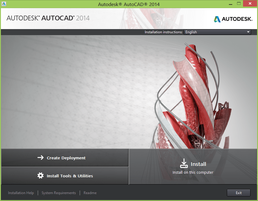
When you download AutoCAD 2014 and run the exe you will find the new Autodesk Self Extract. Too bad that the window cannot be moved and the path cannot be edited in the text box and the exe file cannot be unzipped using for example 7-Zip like it used to for AutoCAD 2013.
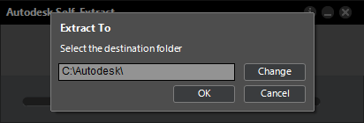
Here is what the setup look like.
NEW: Deployment path length validation. Deployments created on Windows can exceed the maximum path length for the operating system, especially if they are nested deeply within a directory structure. To reduce the chances of exceeding this limit, Autodesk shortened many of the deployment directory names, and implemented a path length check that alerts the user if a path is too long, and by how many characters.
NEW: Combined 32- and 64-bit deployments. For networks that include both 32- and 64-bit computers, network administrators can create a combined deployment that will determine the computer type and automatically install the matching product versions. You must first create separate 32- and 64-bit deployments before you create the combined deployment. In the deployment Tools folder, double-click the CombineDeploy.exe tool.
NEW: Scripted uninstall file. Each deployment now includes a batch file that you can use to automatically uninstall all or part of a deployment. The batch file acad2014_Uninstall is found in the SMS_SCCM scripts folder of the deployment.
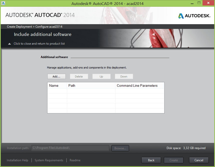
NEW: Including additional software in deployments. When you select the Autodesk products to include in a deployment, you can also include third-party products, add-ins from the App Store, language packs, and other .MSI or .EXE packages.
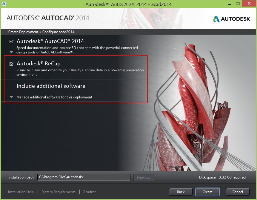
Include additional software.
Combined 32- and 64-bit deployments. For networks that include both 32- and 64-bit computers, network administrators can create a combined deployment that will determine the computer type and automatically install the matching product versions.
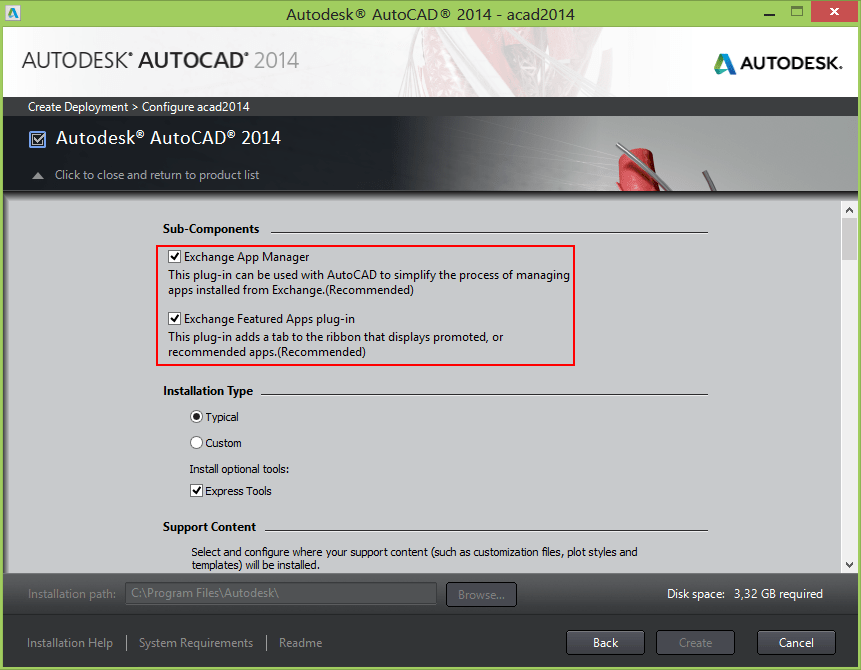
Sub-Components
- Exchange App Manager
- Exchange Featured Apps plug-in
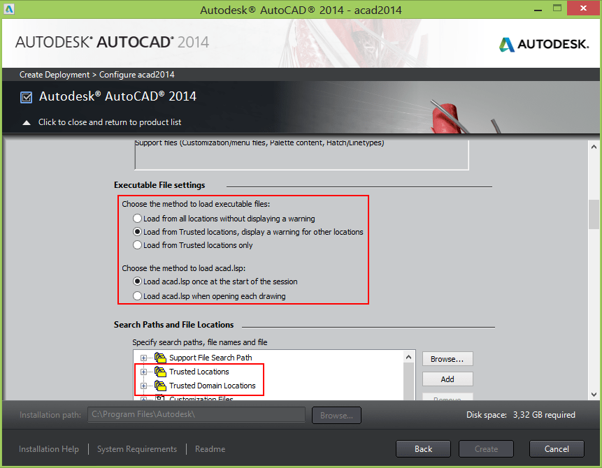
Executable File settings
Choose the methods to load executable files:
- Load from all locations without displaying a warning
- Load from Trusted locations, displaying a warning for other locations
- Load from Trusted locations only
Choose the method to load acad.lsp:
- Load acad.lsp once at the start of the session
- Load acad.lsp when opening each drawing
Search Paths and File Locations
- Trusted Locations
- Trusted Domain Locations
When creating a deployment don't browse for search paths if multiple ones are added as they are not saved as they should. Copy and paste the paths from Windows Explorer instead.
And the installation is in progress.
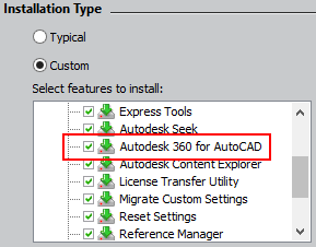
Autodesk 360
The feature Autodesk 360 for AutoCAD that can be optionally installed or not is only affecting the Ribbon tab Autodesk 360 within AutoCAD and not the actual Autodesk 360 installer. Out-of-the-box Autodesk 360 is always installed.
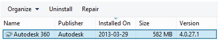
After installing AutoCAD 2014 you can manually uninstall Autodesk 360.
But the setup.ini file or the deplayment ini file can be edited to avoid having Autodesk 360 installed when running the setup or deployment.
Change the below line:
POSTREQUISITE=ACAD_PSPACK;ADSYNC;ACADSKETCHUPIMPORT
to
POSTREQUISITE=ACAD_PSPACK;ACADSKETCHUPIMPORT
Windows 8 and the .NET 3.5 Requirement
Some Autodesk products require Microsoft DirectX, which, in turn, requires the Microsoft .NET Framework. But Windows 8 has enforced restrictions on installing .NET 3.5 and earlier versions from local media. Therefore, Autodesk products require Internet access so that Windows updates can install or enable the .NET Framework.
If the Autodesk installer is unable to install .NET 3.5 or an earlier version on Windows 8, the following message appears:
An Internet connection is required to install a Windows component. Please connect and re-launch the installer.
The .NET installation is prevented by any of the following conditions:
- An Internet connection is not available during installation.
- The computer is configured to use Windows Server Update Services (WSUS) instead of Windows Update.
- The Windows 8 update for Microsoft Security Advisory ( 2749655) is not installed.
If any of these conditions cannot be resolved, then the System Administrator or user must manually enable .NET 3.5 on each Windows 8 computer before running the Autodesk installer. For more information and procedures, see the following MSDN article.
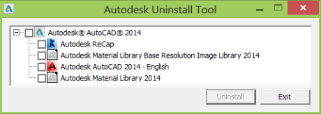
Autodesk Uninstall Tool
To uninstall several products or an entire suite, it is recommended that you use the Autodesk Uninstall Tool, which you can launch from the list of products on your computer.
Access to the list varies by version of Windows:
•Windows 7 or XP: Click Start menu > All Programs.
•Windows 8: Right-click Start screen > All Apps.
In the tool window, select the products to be uninstalled. If uninstalling one of your selected products would prevent another product from operating correctly, you will see a warning message about also uninstalling the related products. The Uninstall Tool does not uninstall service packs or locally installed Help files.
API and more for Programmers
Use either Visual Studio 2010 or 2012 for ObjectARX and .NET development.
The following new or changed features are now exposed through the API:
- Connected Desktop - Design Feed
- Geolocation
- Point Cloud
ObjectARX applications should target the VC100 compiler installed with VS2010 using the Platform Toolset feature.
.NET applications should target Framework 4.0.
The following outlines what needs to be done to use custom programs developed for an AutoCAD-based product released prior to AutoCAD 2014:
- Scripts and Action Macros– No changes should be needed, unless the script or action macro uses a command or system variable that has been deprecated or changed in the product.
- AutoLISP– No changes should be needed, unless it uses a command or system variable that has been deprecated or changed in the product.
- .NET– Programs developed for AutoCAD 2013-based products do not need to be updated unless you want to take advantage of the latest changes to the API. Programs developed for AutoCAD 2012-based products and earlier need to be recompiled.
- ObjectARX– Programs developed for AutoCAD 2013-based products do not need to be updated unless you want to take advantage of the latest changes to the API. Programs developed for AutoCAD 2012-based products and earlier need to be recompiled.
Assume the TRUSTEDPATH your app is installed to is read only when a CAD operator is using your app. Don’t try to save files (such as config files or temporary files) to the same folder as your app.
The acad.exe command line switch /safemode prevents all executable files from loading and executing in the current session. This switch is useful for stopping and locating malicious executable code.
Note! The Express Tools and some AutoCAD command tools are also prevented from functioning, so this switch should be used only in emergency situations.
Minor version number incremented to R19.1
CLAYOUT system variable sets the current layout. The value for CLAYOUT consists of two parts: the layout name and the handle. For example
Enter new value for CLAYOUT <"Model*22">:
In this case, Model is the name of the layout and 22 is the handle (the * is a separator). You can switch to this tab either by entering Model or *22. The handle is exposed as a convenience for developers.
ATTDIA system variable updated. Default value changed from 0 (off) to 1 (on).
See more new and updated system variables.
You can use the product ProgID to create a new instance of the AutoCAD application ("AutoCAD.Application"), and specify the major and minor number of the release to restrict your application to a specific release or all the releases that are binary compatible with each other.
For example,
- CreateObject("AutoCAD.Application.19")attempts to create a new instance of AutoCAD 2013 or AutoCAD 2014. The last used release of the product is what the new instance is based on.
- CreateObject("AutoCAD.Application.19.1")attempts to create a new instance of AutoCAD 2014 only even if another release of the product is installed.
JavaScript API
Load JavaScript-enabled HTML into a palette or dialog. Use acjsDefun() to expose your own arx functions and Editor.DefunJS() in .NET.
Functions receive JSON string as parameter.
Geolocation API
Basic level API for the GeoLocation feature. Create/Modify geo-referenced AutoCAD drawing. Use class AcDbGeoData in ObjectARX. Use class GeoLocationData in AutoCAD.NET.
VBA
The VBA enabler is now true 64bit. The performance problems, with previous releases of 64bit AutoCAD when using VBA, should be now be gone.
32bit VB6 controls will fail on 64bit.
XP 64-bit does not support VBA.
VBA 7.1 is the version of VBA.
Available as a separate download.
The ActiveX/VBA document has also been updated as well and can be found installed on your local drive at:
- %ProgramFiles%\Common Files\Autodesk Shared\acad_aag.chm - Developer's Guide
- %ProgramFiles%\Common Files\Autodesk Shared\acadauto.chm - Reference Guide
AutoLISP
findtrustedfile is a new function - Searches the AutoCAD trusted file paths for the specified file. Syntax: (findtrustedfile filename)
The findtrustedfile function makes no assumption about the file type or extension of filename.
Argument is filename - Name of the file to be searched for.
Return Values
A string containing the fully qualified file name; otherwise nil, if the specified file is not found.
Examples
If the trusted locations and support search file paths contains C:\myapps, and abc.lsp is contained in the path, the function retrieves the path name:
Command: (findtrustedfile "abc.lsp")
"C:\\myapps\\abc.lsp"
If the folder in which abc.lsp is not present in both the trusted locations and support search file paths, findtrustedfile returns nil.
Command: (findtrustedfile "abc.lsp")
nil
showHTMLModalWindow is a new function - Displays a modal window with a HTML document; use in conjunction with the new JavaScript API.
findfile has been updated - Searches the AutoCAD support and trusted file paths. Function was updated to search the new trusted applications paths.
The AutoCAD ActiveX library has been updated to remove methods and properties that were originally defined for 64-bit support.
The following outlines the additions and changes made to the ActiveX API in AutoCAD 2014 and AutoCAD 2014-based products.
Enums
No changesClasses
IAcadApplication
        HWND32 - Property (Obsolete; use HWND)
IAcadDatabase
        ObjectIDToObject32 - Method
           (Obsolete; use ObjectIDToObject)
IAcadDocument
        ObjectIDToObject32 - Method
           (Obsolete; use ObjectIDToObject)
        HWND32 - Property (Obsolete; use HWND)
IAcadIDPair
        Key32 - Property (Obsolete; use Key)
        Value32 - Property (Obsolete; use Value)
IAcadMLeader
        GetBlockAttributeValue32 - Method
           (Obsolete; use GetBlockAttributeValue)
        SetBlockAttributeValue32 - Method
           (Obsolete; use SetBlockAttributeValue)
IAcadObject
        ObjectID32 - Property (Obsolete; use ObjectID)
        OwnerID32 - Property (Obsolete; use OwnerID)
IAcadPViewport
        LabelBlockId32 - Property (Obsolete; use OwnerID)
IAcadTable
        GetBlockAttributeValue232 - Method
           (Obsolete; use GetBlockAttributeValue2)
        GetBlockAttributeValue32 - Method
           (Obsolete; use GetBlockAttributeValue)
        GetBlockTableRecordId232 - Method
           (Obsolete; use GetBlockTableRecordId2)
        GetBlockTableRecordId32 - Method
           (Obsolete; use GetBlockTableRecordId)
        GetFieldId232 - Method (Obsolete; use GetFieldId2)
        GetFieldId32 - Method (Obsolete; use GetFieldId)
        GetGridLinetype32 - Method
           (Obsolete; use GetGridLinetype)
        SetBlockAttributeValue232 - Method
           (Obsolete; use SetBlockAttributeValue2)
        SetBlockAttributeValue32 - Method
           (Obsolete; use SetBlockAttributeValue)
        SetBlockTableRecordId232 - Method
           (Obsolete; use SetBlockTableRecordId2)
        SetBlockTableRecordId32 - Method
           (Obsolete; use SetBlockTableRecordId)
        SetFieldId232 - Method (Obsolete; use SetFieldId2)
        SetFieldId32 - Method (Obsolete; use SetFieldId)
        SetGridLinetype32 - Method
           (Obsolete; use SetGridLinetype)
IAcadTableStyle
        GetTextStyleId32 - Method (Obsolete; use GetTextStyleId)
        SetTemplateId32 - Method (Obsolete; use SetTemplateId)
        SetTextStyleId32 - Method (Obsolete; use SetTextStyleId)
        TemplateId32 - Property (Obsolete; use TemplateId)
IAcadUtility
        GetSubEntity32 - Method (Obsolete; use GetSubEntity)
        ObjectId32ToObjectIdString - Method
                  (Obsolete; use ObjectIdToObjectIdString)
IAcadView
        LayoutID32 - Property (Obsolete; use LayoutID)
What's New in .NET ObjectARX for AutoCAD 2014.
| Application.ShowModalWindow Method (IntPtr, Uri) | Use this function to launch a modal dialog with the specified URI. The window hosts a browser window which displays the html page. |
| Application.ShowModalWindow Method (IntPtr, Uri, [MarshalAs(UnmanagedType.U1)] bool) | Use this function to launch a modal dialog with the specified URI. The window hosts a browser window which displays the html page. |
| Application.ShowModalWindow Method (Uri) | Use this function to launch a modal dialog with the specified URI. The window hosts a browser window which displays the html page. |
| Application.ShowModelessWindow Method (IntPtr, Uri) | Use this function to launch a modeless dialog with the specified URI. The window hosts a browser window which displays the html page. |
| Application.ShowModelessWindow Method (IntPtr, Uri, [MarshalAs(UnmanagedType.U1)] bool) | Use this function to launch a modeless dialog with the specified URI. The window hosts a browser window which displays the html page. |
| Application.ShowModelessWindow Method (Uri) | Use this function to launch a modeless dialog with the specified URI. The window hosts a browser window which displays the html page. |
| Document.IsNamedDrawing Property | Returns true if the drawing for this document is a named file on the disk (as opposed to a new drawing that has not yet been saved). |
| MLeader.Scale Property | Gets or sets the scale for the MLeader. |
| Region.AreaProperties Method | This function calculates the area properties of the Region. All of the values in the returned RegionAreaProperties struct are in the coordinate system specified by origin, xAxis, and yAxis (which must be in WCS coordinates). The function validates the origin, xAxis, and yAxis parameters to ensure that the axes are of unit length and are perpendicular to each other, and that the axes and origin lie in the same plane as the Region. |
| RegionAreaProperties Structure | This class encapsulates the data returned by the AcDbRegion::getAreaProp()ObjectARX function. |
| RegionAreaProperties.Area Property | Returns the area of the Region |
| RegionAreaProperties.Centroid Property | Returns the centroid point of the Region |
| RegionAreaProperties.Extents Property | Returns the extents of the Region |
| RegionAreaProperties.MomentsOfInertia Property | Returns the moments of inertia of the Region |
| RegionAreaProperties.Perimeter Property | Returns the perimeter of the Region. |
| RegionAreaProperties.PrincipalMoments Property | Returns the principal moments of the Region. |
| RegionAreaProperties.ProductOfInertia Property | Returns the product of inertia of the Region |
| RegionAreaProperties.RadiiOfGyration Property | Returns the radii of gyration of the Region |
| Xrecord.Append Method | Allows custom applications to add to the Xrecord without getting the existing data, appending to the end of resbuf chain and setting the data back into the xrecord. appendRbChain is more efficient when it comes to undo recording. |
| XrecordEnumerator.Current Property | Allows callers to modify the resbuf chain inside the AcDbXrecord without having to get/set the whole chain. More efficient in terms of amount of data that needs to be copied and also does partial undo. After calling modifyCurResbuf, AcDbXrecordIterator::getCurResbuf will return the new value. |
| XrecordEnumerator.InsertAtCurrent Method | Allows callers to insert one or more resbufs into the AcDbXrecord without having to get/set the whole chain. More efficient in terms of amount of data that needs to be copied and also does partial undo. After calling insertRbChain, AcDbXrecordIterator::getCurResbuf will return the first item inserted. |
| XrecordEnumerator.RemoveCurrent Method | Allows callers to delete an item from the AcDbXrecord without having to get/set the whole chain. More efficient in terms of amount of data that needs to be copied and also does partial undo. After calling removeResbuf, AcDbXrecordIterator::getCurResbuf will return the first item after the deleted item. You must call AcDbXrecordIterator::done() to determine if the last item was removed. |
| Editor.ApplyCurDwgLayerTableChanges Method | Updates the cached layer data for the current document in the editor. |
| Editor.PostCommandPrompt Method | This function causes AutoCAD to repost the last command prompt message. |
| TextStyle.FromTextStyleTableRecord Method (ObjectId) | Copies the style properties from the TextStyleTableRecord whose ObjectId is AcDbStyleId. |
| TextStyle.FromTextStyleTableRecord Method (string) | Copies the style properties from the TextStyleTableRecord whose name is AcDbStyleName. |
| TextStyle.ToTextStyleTableRecord Method () | Copies the style properties to a TextStyleTableRecord whose name is same as this TextStyle's name. If no such record exists, then one is created. If this TextStyle has no name, then a random name will be generated and used for both this TextStyle and the TextStyleTableRecord. |
| TextStyle.ToTextStyleTableRecord Method (ObjectId) | Copies the style properties to the TextStyleTableRecord whose ObjectId is AcDbStyleId. |
| TextStyle.ToTextStyleTableRecord Method (string) | Copies the style properties to the TextStyleTableRecord whose name is AcDbStyleName. |
| Window.Focus Method | This method sets focus to the window on which it is called. It returns true if it successfully sets the focus to that window, otherwise it returns false. |
| To use this method to set the current drawing window to have focus you would use: Application.DocumentManager. MdiActiveDocument.Window.Focus() |
|
| Application.LoadJSScript Method | Use this function to load and execute JavaScript without a palette. |
AutoCAD 2014 System requirements
Note that Windows Vista is not supported by Autodesk for AutoCAD 2014. Autodesk to cease support of Windows Vista even though Microsoft changed their mind Autodesk didn’t follow.
It is possible to install and run AutoCAD 2014 on Windows Vista but you're on your own. You first need to ensure that .NET 3.5 SP1 is installed. To install AutoCAD 2014 right mouse click on the Setup.exe > Properties > Compatibility Tab > Show settings for all users > Run this program in compatibility mode for: Windows XP (Service Pack 2).
As always with system requirements these are minimal requirements forAutoCAD to run. For professional usage you surely want to have much better hardware.
FlexNet version 11.11 for Autodesk Network License Manager
Supported operating systems are:
Microsoft Windows Server 2008 and 2008 R2 32-bit and 64-bit
Microsoft Windows Server 2012 32-bit and 64-bit
Windows 7 32-bit and 64-bit
Windows 8 32-bit and 64-bit
More details here as well as Linux System Requirements and Mac System Requirements.
AutoCAD 2014 System Requirements
AutoCAD 2014 System Requirements for 32-bit Workstations
| Description | Requirement |
| Operating system | Service Pack 3 (SP3) or later of the following: •Microsoft® Windows® XP Professional •Microsoft® Windows® XP Home The following operating systems: •Microsoft Windows 7 Enterprise •Microsoft Windows 7 Ultimate •Microsoft Windows 7 Professional •Microsoft Windows 7 Home Premium •Microsoft Windows 8 •Microsoft Windows 8 Pro •Microsoft Windows 8 Enterprise |
| Browser | Internet Explorer® 7.0 or later |
| Processor | Windows XP: Intel® Pentium® 4 or AMD Athlon™ Dual Core, 1.6 GHz or Higher with SSE2 technology Windows 7 and Windows 8: Intel Pentium 4 or AMD Athlon Dual Core, 3.0 GHz or Higher with SSE2 technology |
| Memory | 2 GB RAM (4 GB Recommended) |
| Display resolution | 1024 x 768 (1600 x 1050 or higher recommended) with True Color |
| Disk Space | Installation 6.0 GB |
| Pointing Device | MS-Mouse compliant |
| Media | Download and Installation from DVD |
| Additional requirements for 3D Modeling | Intel Pentium 4 processor or AMD Athlon, 3.0 GHz or greater or Intel or AMD Dual Core processor, 2.0 GHz or greater 4 GB RAM 6 GB free hard disk available not including installation requirements 1280 x 1024 True color video display adapter 128 MB or greater, Pixel Shader 3.0 or greater, Direct3D® capable workstation class graphics card. Note: 64-bit Operating Systems are recommended if you are working with Large Datasets, Point Clouds and 3D Modeling - please refer to the AutoCAD 64-bit System Requirements for more information. |
| .NET Framework | .NET Framework Version 4.0, Update 1 |
AutoCAD 2014 System Requirements for 64-bit Workstations
| Description | Requirement |
| Operating system | Service Pack 2 (SP2) or later of the following: •Microsoft® Windows® XP Professional* The following operating systems: •Microsoft Windows 7 Enterprise •Microsoft Windows 7 Ultimate •Microsoft Windows 7 Professional •Microsoft Windows 7 Home Premium •Microsoft Windows 8 •Microsoft Windows 8 Pro •Microsoft Windows 8 Enterprise *VBA is not supported on Windows XP Professional |
| Browser | Internet Explorer® 7.0 or later |
| Processor | AMD Athlon 64 with SSE2 technology AMD Opteron™ with SSE2 technology Intel Xeon® with Intel EM64T support and SSE2 Intel Pentium 4 with Intel EM64T support and SSE2 technology |
| Memory | 2 GB RAM (4 GB Recommended) |
| Display resolution | 1024 x 768 (1600 x 1050 or higher recommended) with True Color |
| Disk Space | Installation 6.0 GB |
| Pointing Device | MS-Mouse compliant |
| Media | Download and Installation from DVD |
| Additional requirements for 3D Modeling | 4 GB RAM or more 6 GB free hard disk available not including installation requirements 1280 x 1024 True color video display adapter 128 MB or greater, Pixel Shader 3.0 or greater, Direct3D® capable workstation class graphics card. |
| .NET Framework | .NET Framework Version 4.0, Update 1 |
Still missing
Still missing. Wish list for the next time.
Using fence it would be possible to select an object with a linetype with spaces when the fence is hitting the space in the linetype.
Preview handlerfor Vista and Outlook 2007, Outlook 2010 and Outlook 2013.
In sheet set manager it used to work adding the Unicode \U+000A to force a new line (line feed) in properties so it showed on say two lines on the drawing. Now it gives a new line using SHX fonts and nothing at all with TTF fonts.
Add support to find solid and gradient hatches with the Matchprop command as easily as you can with the Erase command and solid hatches.
If you have a select object command like Erase and move it over a solid or gradhatch it is not always showing that the object is selectable (selection preview) even though it is if you try to click on it.
In dialog boxes like the Open dialog box it should be possible to save changes like columns to show, width, sorting, grouping etc.
Ability to change background color and size of DWG previews in for example the Open dialog box.
Be able to rotate OLE objects.
Easy way to change the length of the extension lines on dimensions. As a complement to DIMFXL and DIMFXLON having grips to easily adjust the length could help in some cases.
Variable extension origin offsets. So, instead of a fixed value for DIMEXO, one could have a DIMEXO1 and DIMEXO2 that also are accessible through grip editing.
Improve the functionality to show real symbols for mtext and also delete any that are not used. It is now only possible to add new ones through the registry. Personal Mtext Symbols.
Having the help window linked to the main application window is not always wanted. Give us a better option. One suggestion is to have the help window completely separated from the main application.
Add some kind of table of contents to the help system. By functionality, by command, variable, etc.
Moving a sheet view from one sheet to another so that existing callouts get updated rather than broken.
Edit Page Setups For Multiple Layouts using CTRL+Select and/or SHIFT+ to Select the appropriate layouts. (on AUGI AutoCAD Top Ten Wish List 2012)
Autodesk Self Extract. Too bad that the window cannot be moved and the path cannot be edited in the text box and the exe file cannot be unzipped using for example 7-Zip like it used to for AutoCAD 2013. I wish ISO was an option to download.
Be able to have have the File Tabs at the bottom as an option.
Dynamic input should support everything that the command line offers. Internet Search, Help, Content and Categories.
Dragging a layout tab into Sheet Set Manager does not work if SSM is docked.
Add the ability to create custom subset properties in Sheet Set Manager. Subset custom properties.
VBALOAD dialog to be resizable and remember its size.
It would be good to have drag and drop of a drawing (or DST) to work to open it when dropping it on the File Tabs.
Existing bugs
Existing bugs, defects, feature limitation or other issues.
AutoCAD 2014 SP1 introduced the AutoCAD Educational Version - Plot Stamp Not Detected bug!
Drawing Revision number as seen in DWGPROPS is used when adding a Sheet List Table and there is no way to show the sheet property Revision number. Revision date, Purpose and Category cannot be added to the table either.
Autodesk 360
If you don't use or need Autodesk 360, uninstall it. Se how here.
It has been found to crash Windows Explorer. In the Windows Event Viewer the following can be found:
Faulting application name: Explorer.EXE
Faulting module name: QtCore_Ad_SyncNs_4.dll_unloaded, version: 0.0.0.0
Faulting module path: QtCore_Ad_SyncNs_4.dll
The shell stopped unexpectedly and explorer.exe was restarted.
Within AutoCAD when I tried to Sign Out I got this error and AutoCAD crashed: AutoCAD Error Aborting: ERROR: Unhandled Access Violation Reading 0x0040 Exception at 6949f0dfh
AutoCAD Text Window
There is no horizontal scroll bar or word wrap in the AutoCAD Text Window (CTRL+F2 if undocked). Word wrap works if the command line is undocked though and F2 is pressed.

Creating Deployment problem
When creating a deployment don't browse for search paths if multiple ones are added as they are not saved as they should.
VBA
When the VBA environment is loaded in one way or the other it can cause a big slowdown (10 times slower or more) of commands like QSAVE. This happens even when no code is loaded at all.
Visual LISP
vla-get-area function on the reactor owner cannot be used within a callback function as it will trigger the callback function creating an endless loop of calls. Workaround is to use vlax-curve-getArea.
Removed
Removed
Inventor Fusion import and editing functionality has been removed. But you can get involved in the beta program of Autodesk Fusion 360.
There seems to not be any Autodesk Design Review 2014. Autodesk Design Review 2013 can still be used for DWF’s created with AutoCAD 2014 as the format is the same. Autodesk intends to replace the Design Review application with cloud-based services so Autodesk Design Review 2013 might be the last release.
Tips & Tricks
Tips & Tricks
AutoCAD 2014 also is referred to as ACAD2014 or ACAD 2014.
AutoCAD 2014 product key is 001F1.
Available AutoCAD 2014 languages : English, Brazilian Portuguese, French, German, Italian, Korean, Simplified Chinese, Spanish and Traditional Chinese. Japanese is also available but not as part of the AutoCAD 2014 Language Pack. Russian, Czech, Hungarian and Polish are missing so far but will be added.
Default command line to start AutoCAD 2014: "C:\Program Files\Autodesk\AutoCAD 2014\acad.exe" /product ACAD /language "en-US"
How to to change the license from Standalone to Network:
The registry location to change the installation from Standalone to Network for AutoCAD 2014 is here:
HKEY_LOCAL_MACHINE\SOFTWARE\Autodesk\AutoCAD\R19.1\ACAD-D001\AdLM
ACAD-D001 is for vanilla AutoCAD.
Change the type for the installation using any of these values:
1 – Network
2 – Standalone
3 – Multiseat Standalone
In vanilla AutoCAD:
Command: _vernum
_VERNUM = "I.18.0.0 (UNICODE)" (read only)
AutoCAD 2014 SP1:
_VERNUM = "I.108.0.0 (UNICODE)" (read only)
Readme
Readme
This readme contains the latest information for Autodesk® AutoCAD® 2014 and Autodesk® AutoCAD LT® 2014. For reference, save or print this document.
It is strongly recommended that you read this entire document before you install this product.
Install
- Recommended: Install all Windows Updates before installing the product.
Design Feed
- The Design Feed palette might not update immediately after you save a drawing in Autodesk® 360. To accelerate the save operation, right-click the Autodesk 360 icon, available from the Windows taskbar, and select Sync Now.
Autodesk 360 Sync
- Before you reopen a file that you have saved and closed in Autodesk 360, allow additional time for the automatic sync feature to set the new path for linked files such as xrefs. If the repathing process is not complete, the drawing file will be locked when you open it, and you might get an error.
Point Cloud
- You cannot view certain point cloud files in AutoCAD if your graphics card does not support OpenGL® 3.3 or later. In addition, you cannot view these files in a Windows remote desktop session. (Points clouds are not available in AutoCAD LT.)
- See the Autodesk® ReCap Readme for more information.
Product Help
- Product Help is available online and is not installed with the product by default. If you do not have access to the Web and want to install Help with the product, you can start the Help installation at the end of the product installation. After you open the product, you can also select Download Offline Help from the Help menu.
Welcome Screen
- You must have Adobe® Flash® Player installed to view some types of video content. If you cannot install it directly from the Welcome Screen, you can install it from the Adobe Flash download page. If prompted to select the Flash Player version to install, be sure to select Flash Player For Other Browsers for best compatibility.
Video Content
- QuickTime is required for viewing some types of video content. If videos fail to play, install QuickTime directly from the Apple QuickTime download page.
Updates & Service Packs
Updates & Service Packs.
- Model Documentation Hotfix for 64-bit Windows 8.1
- AutoCAD 2014 Service Pack 1
- Autodesk 360 desktop companion Update 3
- Autodesk® AutoCAD® Code Execution Vulnerability – Security Hotfix
- Windows crash during license authorization Hotfix
- AutoCAD® DGN Hotfix
- Scale List Cleanup Utility for AutoCAD 2013/2014
- Autodesk® AutoCAD® Graphics Hotfix
- AutoCAD 2014 Custom Entity Hotfix
- Regapp ID Cleanup Utility for AutoCAD 2013/2014
- AutoCAD Reality Capture Memory Leak Hotfix
- Autodesk IPv6 Network License Manager for Windows
- Autodesk IPv4 Network License Manager for Windows
- Autodesk ReCap 1.0 Service Pack 1 For 1.0.43.13 x64 (64-bit)
Autodesk ReCap 1.0 Service Pack 1 For 1.0.43.13 x86 (32-bit)
Improve UI responsiveness; Improve visualization and data streaming performance; Support import of very large ptg files; Support export selection or view to RCS; Improve ZFS import accuracy; Fix compatibility issue with Inventor localized builds; Fix PTS export compatibility with Navisworks; Fix E57 export compatibility with Leica Cyclone; Fix uninstall issue with Factory Design Suite 2013. - VBA for AutoCAD downloads here athttp://www.autodesk.com/vba-download.
- AutoCAD Architecture & AutoCAD MEP 2014 Object Enabler
- Autodesk AutoCAD Plant 3D 2014 Object Enablers
- AutoCAD 2014 Language Packs
If you are are installing...
- AutoCAD 2014 non English version
- Using Windows 8 operating system
You will get a .NET 4 and a .NET 4.5 Language Pack error when installing the product.
The following workaround that will help resolve this issue:
1. Copy the Media contents to a local drive or use a browser downloaded version of software.
2. Copy and backup the setup.ini file and call it: setup-BACKUP.ini.
3. Open file setup.ini from the root folder using a text editor.
4 .Search for (without quotes) “[DOTNET4LANG]” and “[DOTNET45LANG]”
5. Add a new line “IGNORE_FAILURE=YES” for them if found. This line can be added anywhere below “EXE_PARAM=”
AutoCAD Civil 2014 Object Enabler
AutoCAD Civil 2014 Object Enabler ID: DL21825057 The Civil Object Enabler is a freeware application that you can use to access Autodesk AutoCAD Civil 3D drawing files. This release allows object data created in Autodesk AutoCAD Civil 3D 2014
http://usa.autodesk.com/adsk/servlet/ps/dl/item?id=21825057&linkID=9240618&siteID=123112
Published: 2013-May-29 Category: Utilities & Drivers
AutoCAD 2014 Custom Entity Hotfix
AutoCAD 2014 Custom Entity Hotfix ID: DL21484847 This hot fix addresses an issue with the file open command failing when a drawing is opened that contains custom entities with embedded 3D solids. This hotfix applies to the shipping version
http://usa.autodesk.com/adsk/servlet/ps/dl/item?id=21484847&linkID=9240618&siteID=123112
Published: 2013-Apr-10 Category: Updates & Service Packs
Regapp ID Cleanup Utility for AutoCAD 2013/2014
Regapp ID Cleanup Utility for AutoCAD 2013/2014 ID: DL21482832 When you delete an object with Extended Entity Data (xdata), a regapp ID remains in the application ID (APPID) symbol table. When a file contains excess unreferenced regapp IDs
http://usa.autodesk.com/adsk/servlet/ps/dl/item?id=21482832&linkID=9240618&siteID=123112
Published: 2013-Apr-02 Category: Updates & Service Packs
Scale List Cleanup Utility for AutoCAD 2013/2014
Scale List Cleanup Utility for AutoCAD 2013/2014 ID: DL21482846 When a file contains excess scales, performance may be negatively affected. Eventually, the file may become unusable. To use the file, some scales must be removed. This utility repairs
http://usa.autodesk.com/adsk/servlet/ps/dl/item?id=21482846&linkID=9240618&siteID=123112
Published: 2013-Apr-02 Category: Updates & Service Packs
AutoCAD Architecture & AutoCAD MEP 2014 Object Enabler
AutoCAD Architecture & AutoCAD MEP 2014 Object Enabler ID: DL21383313 AutoCADArchitecture-MEP 2014 OE.exe (exe - 18951Kb) AutoCAD Architecture-MEP 2014 OE x64.exe (exe - 23621Kb) Readme (html - 33Kb)
http://usa.autodesk.com/adsk/servlet/ps/dl/item?id=21383313&linkID=9240618&siteID=123112
Published: 2013-Mar-28 Category: Utilities & Drivers
2014: Cascading Sequences for Autodesk Products
2014 products: AutoCAD 2014 AutoCAD for Mac 2014 AutoCAD Mechanical 2014 AutoCAD P&ID2014 AutoCAD Plant 3D 2014 AutoCAD Design Suite Standard 2014 Autodesk Product Design Suite Standard 2014 Autodesk Factory Design Suite Standard 2014 Autodesk Building
http://usa.autodesk.com/adsk/servlet/ps/dl/item?id=21379174&linkID=9240617&siteID=123112
Published: 2013-Mar-25 Category: Knowledge Base
2014: Product keys for Autodesk products
that are both sold independently and as part of a product suite. For example, installing AutoCAD2014 as a point product requires product key 001F1, but installing AutoCAD 2014 from the Autodesk Product Design Suite Ultimate 2014 requires product key 781F1
http://usa.autodesk.com/adsk/servlet/ps/dl/item?id=21481916&linkID=9240617&siteID=123112
Published: 2013-Apr-01 Category: Knowledge Base
2014: FLEXnet® feature codes for Autodesk products
:00:04 (adskflex) OUT: "40100ARCHDESK_3_3F" user@hostname The feature codes for Autodesk2014 products are as follows: Product Feature Code AutoCAD 2014 86063ACD_2014_0F AutoCADArchitecture 2014 86137ARCHDESK_2014_0F AutoCAD Civil 3D 2014 86173CIV3D_2014_0F
http://usa.autodesk.com/adsk/servlet/ps/dl/item?id=21374698&linkID=9240617&siteID=123112
Published: 2013-Mar-25 Category: Knowledge Base
Autodesk AutoCAD Plant 3D 2014 Object Enablers
Autodesk AutoCAD Plant 3D 2014 Object Enablers ID: DL21330574 Autodesk offers free downloadable enablers that you can use to access, display, and manipulate object data in applications different from their native environment. This provides essential
http://usa.autodesk.com/adsk/servlet/ps/dl/item?id=21330574&linkID=9240618&siteID=123112
Published: 2013-Apr-15 Category: Utilities & Drivers
Open Light 2014 Object Enabler (32-bit and 64-bit)
this object enabler installed, you can share drawings using proxy graphics representations or the Export to AutoCAD command. Open Light 2014 Object Enabler (32-bit) (exe - 2939Kb) Open Light2014 Object Enabler (64-bit) (exe - 3712Kb) Readme (select language
http://usa.autodesk.com/adsk/servlet/ps/dl/item?id=21478037&linkID=9240618&siteID=123112
Published: 2013-Apr-02 Category: Utilities & Drivers
Operating system compatibility for AutoCAD and AutoCAD LT
systems for releases of AutoCAD and AutoCAD LT: AutoCAD 2014 and AutoCAD LT 2014 (current release) OS 32-bit 64-bit Windows® 8 Standard, Enterprise, Professional Standard, Enterprise, Professional Windows® 7 Enterprise, Ultimate, Professional, Home Premium
http://usa.autodesk.com/adsk/servlet/ps/dl/item?id=14078105&linkID=9240617&siteID=123112
Published: 2013-Mar-25 Category: Knowledge Base
System requirements for AutoCAD
System requirements for AutoCAD ID: TS15412189 This document provides the system requirements for Autodesk® AutoCAD® Products. AutoCAD 2014 System Requirements For 32-bitAutoCAD 2014 For 64-bit AutoCAD 2014 Additional requirements for large
http://usa.autodesk.com/adsk/servlet/ps/dl/item?id=15412189&linkID=9240617&siteID=123112
Published: 2013-May-15 Category: Knowledge Base
AutoCAD Reality Capture Memory Leak Hotfix
AutoCAD Reality Capture Memory Leak Hotfix ID: DL21475673 This hotfix addresses a memory leak issue when using the Reality Capture (Point Clouds) feature. This hotfix applies to the shipping version of Autodesk AutoCAD 2014, and AutoCAD 2014-based
http://usa.autodesk.com/adsk/servlet/ps/dl/item?id=21475673&linkID=9240618&siteID=123112
Published: 2013-Mar-28 Category: Updates & Service Packs
Windows crash during license authorization of Autodesk 2014 product
Windows crash during license authorization of Autodesk 2014 product ID: TS21825687
FATAL ERROR: Unhandled Access Violation Reading 0x0000 Exception at eaf28ea0h
Issue This error occurs when a computer does not have the hardware serial number in the BIOS. Two indications of the issue are described below: 1. When launching
http://usa.autodesk.com/adsk/servlet/ps/dl/item?id=21825687&linkID=9240617&siteID=123112
Published: 2013-May-30 Category: Knowledge Base
Autodesk Fabrication CADmep 2014 Object Enabler
Autodesk Fabrication CADmep 2014 Object Enabler ID: DL21540623 The Autodesk Fabrication CADmep Object Enabler is a freeware application that you can use to access Autodesk Fabrication CADmep 3D drawing files. This release allows object data
http://usa.autodesk.com/adsk/servlet/ps/dl/item?id=21540623&linkID=9240618&siteID=123112
Published: 2013-Apr-23 Category: Utilities & Drivers
Autodesk 360 is not upgraded to latest version when installing Autodesk Product Design Suite 2014
Autodesk 360 is not upgraded to latest version when installing Autodesk Product Design Suite 2014ID: TS21505941 Issue Autodesk Inventor 2014 installs an older version (4.0.27.1) of Autodesk 360 (the live update function fails to update the newer
http://usa.autodesk.com/adsk/servlet/ps/dl/item?id=21505941&linkID=9240617&siteID=123112
Published: 2013-Apr-28 Category: Knowledge Base
Autodesk Utility Design 2009: side-by-side installation with AutoCAD 2010 or later versions
Autodesk Utility Design 2009: side-by-side installation with AutoCAD 2010 or later versions ID: TS15665715 Issue After installing AutoCAD 2010 or 2011, or another AutoCAD-based 2010 or 2011 product, Autodesk Utility Design 2009 is giving errors
http://usa.autodesk.com/adsk/servlet/ps/dl/item?id=15665715&linkID=9240617&siteID=123112
Published: 2010-Sep-09 Category: Knowledge Base
How to find your serial number and product key in Subscription Center
as working correctly on Microsoft Windows® 7 operating system. Product Support will provide its best effort to assist customers who have issues with products that have not been tested. Autodesk 2014products supported on Windows 7 Unless noted otherwise
http://usa.autodesk.com/adsk/servlet/ps/dl/item?id=21374508&linkID=9240617&siteID=123112
Published: 2013-Mar-25 Category: Knowledge Base
Education Community Serial Number FAQs
-specific, and can result in activation errors if the wrong key is entered. Find a list of all Product Keys by referencing the following solutions: 2014: Product keys for Autodesk products 2013: Product keys for Autodesk products 2012: Product keys for Autodesk products
http://usa.autodesk.com/adsk/servlet/ps/dl/item?id=20398445&linkID=9240617&siteID=123112
Published: 2012-Sep-02 Category: Knowledge Base
Windows 8 Support for Autodesk products
Windows 8 Support for Autodesk products ID: TS19048377 Issue You want to know which Autodesk products are supported on Microsoft Windows® 8. Autodesk 2014 products Please check the system requirements for your product to verify compatibility
http://usa.autodesk.com/adsk/servlet/ps/dl/item?id=19048377&linkID=9240617&siteID=123112
Published: 2013-May-15 Category: Knowledge Base
Educational Plot Stamp Removal Issues
Educational Plot Stamp Removal Issues ID: TS17886605 Issue When plotting a drawing that was created in—or that contains drawing data that was created in—an Educational (Student and Faculty) version of AutoCAD or an AutoCAD-based program
http://usa.autodesk.com/adsk/servlet/ps/dl/item?id=17886605&linkID=9240617&siteID=123112
Published: 2011-Oct-17 Category: Knowledge Base
Linetype Scale (MSLTSCALE and PSLTSCALE)
Linetype Scale (MSLTSCALE and PSLTSCALE) ID: TS14437056 Issue: You have a linetype that shows properly in paper space but not correct in Model space. Solution: There are two system variables introduced in AutoCAD 2008 version: MSLTSCALE
http://usa.autodesk.com/adsk/servlet/ps/dl/item?id=14437056&linkID=9240617&siteID=123112
Published: 2010-Jan-24 Category: Knowledge Base
Cascading Sequences for Autodesk 2014 Products
AutoCAD 2014
AutoCAD for Mac 2014
AutoCAD Mechanical 2014
AutoCAD P&ID 2014
AutoCAD Plant 3D 2014
AutoCAD Design Suite Standard 2014
Autodesk Product Design Suite Standard 2014
Autodesk Factory Design Suite Standard 2014
Autodesk Building Design Suite Standard 2014
Autodesk Infrastructure Design Suite Standard 2014
Autodesk Plant Design Suite Standard 2014
AutoCAD Design Suite Premium 2014
Autodesk Product Design Suite Premium 2014
Autodesk Factory Design Suite Premium 2014
AutoCAD Revit Architecture Suite 2014
AutoCAD Revit Structure Suite 2014
AutoCAD Revit MEP Suite 2014
Autodesk Building Design Suite Premium 2014
Autodesk Infrastructure Design Suite Premium 2014
Autodesk Plant Design Suite Premium 2014
AutoCAD Design Suite Ultimate 2014
Autodesk Product Design Suite Ultimate 2014
Autodesk Factory Design Suite Ultimate 2014
Autodesk Building Design Suite Ultimate 2014
Autodesk Infrastructure Design Suite Ultimate 2014
Autodesk Plant Design Suite Ultimate 2014
Autodesk Design Academy 2014
Autodesk Product Design Suite for Education 2014
Autodesk Education Master Suite 2014
AutoCAD Architecture 2014
Autodesk Factory Design Suite Standard 2014
Autodesk Building Design Suite Standard 2014
Autodesk Factory Design Suite Premium 2014
AutoCAD Revit Architecture Suite 2014
Autodesk Building Design Suite Premium 2014
Autodesk Factory Design Suite Ultimate 2014
Autodesk Building Design Suite Ultimate 2014
Autodesk Design Academy 2014
Autodesk Education Master Suite 2014
AutoCAD Civil 3D 2014
Autodesk Infrastructure Design Suite Premium 2014
Autodesk Infrastructure Design Suite Ultimate 2014
Autodesk Design Academy 2014
Autodesk Education Master Suite 2014
AutoCAD ecscad 2014
Autodesk Product Design Suite Premium 2014
Autodesk Product Design Suite Ultimate 2014
Autodesk Education Master Suite 2014
AutoCAD Electrical 2014
Autodesk Product Design Suite Premium 2014
Autodesk Product Design Suite Ultimate 2014
Autodesk Product Design Suite for Education 2014
Autodesk Education Master Suite 2014
AutoCAD LT 2014
AutoCAD LT for Mac 2014
AutoCAD LT Civil Suite 2014
AutoCAD Inventor LT Suite 2014
AutoCAD Revit LT Suite 2014
AutoCAD Map 3D 2014
Autodesk Infrastructure Design Suite Standard 2014
Autodesk Infrastructure Design Suite Premium 2014
Autodesk Infrastructure Design Suite Ultimate 2014
Autodesk Education Master Suite 2014
AutoCAD Mechanical 2014
Autodesk Product Design Suite Standard 2014
Autodesk Factory Design Suite Standard 2014
Autodesk Product Design Suite Premium 2014
Autodesk Factory Design Suite Premium 2014
Autodesk Product Design Suite Ultimate 2014
Autodesk Factory Design Suite Ultimate 2014
Autodesk Design Academy 2014
Autodesk Product Design Suite for Education 2014
Autodesk Education Master Suite 2014
AutoCAD MEP 2014
Autodesk Building Design Suite Standard 2014
AutoCAD Revit MEP Suite 2014
Autodesk Building Design Suite Premium 2014
Autodesk Building Design Suite Ultimate 2014
Autodesk Education Master Suite 2014
AutoCAD P&ID 2014
AutoCAD Plant 3D 2014
Autodesk Plant Design Suite Standard 2014
Autodesk Plant Design Suite Premium 2014
Autodesk Plant Design Suite Ultimate 2014
Autodesk Education Master Suite 2014
AutoCAD Plant 3D 2014
Autodesk Plant Design Suite Premium 2014
Autodesk Plant Design Suite Ultimate 2014
Autodesk Education Master Suite 2014
AutoCAD Raster Design 2014
AutoCAD Design Suite Standard 2014
Autodesk Product Design Suite Standard 2014
Autodesk Factory Design Suite Standard 2014
Autodesk Building Design Suite Standard 2014
Autodesk Infrastructure Design Suite Standard 2014
Autodesk Plant Design Suite Standard 2014
AutoCAD Design Suite Premium 2014
Autodesk Product Design Suite Premium 2014
Autodesk Factory Design Suite Premium 2014
Autodesk Building Design Suite Premium 2014
Autodesk Infrastructure Design Suite Premium 2014
Autodesk Plant Design Suite Premium 2014
AutoCAD Design Suite Ultimate 2014
Autodesk Product Design Suite Ultimate 2014
Autodesk Factory Design Suite Ultimate 2014
Autodesk Building Design Suite Ultimate 2014
Autodesk Infrastructure Design Suite Ultimate 2014
Autodesk Plant Design Suite Ultimate 2014
Autodesk Product Design Suite for Education 2014
Autodesk Education Master Suite 2014
AutoCAD Structural Detailing 2014
Autodesk Building Design Suite Standard 2014
AutoCAD Revit Structure Suite 2014
Autodesk Building Design Suite Premium 2014
Autodesk Plant Design Suite Premium 2014
Autodesk Building Design Suite Ultimate 2014
Autodesk Plant Design Suite Ultimate 2014
Autodesk Education Master Suite 2014
Autodesk 3ds Max 2014
Autodesk 3ds Max Entertainment Creation Suite Standard 2014
Autodesk 3ds Max Entertainment Creation Suite Premium 2014
Autodesk Entertainment Creation Suite Ultimate 2014
Autodesk Animation Academy 2014
Autodesk Entertainment Creation Suite For Education 2014
Autodesk 3ds Max Design 2014
AutoCAD Design Suite Premium 2014
Autodesk Product Design Suite Premium 2014
Autodesk Factory Design Suite Premium 2014
Autodesk Building Design Suite Premium 2014
Autodesk Infrastructure Design Suite Premium 2014
Autodesk Plant Design Suite Premium 2014
AutoCAD Design Suite Ultimate 2014
Autodesk Product Design Suite Ultimate 2014
Autodesk Factory Design Suite Ultimate 2014
Autodesk Building Design Suite Ultimate 2014
Autodesk Infrastructure Design Suite Ultimate 2014
Autodesk Plant Design Suite Ultimate 2014
Autodesk Design Academy 2014
Autodesk Product Design Suite for Education 2014
Autodesk Education Master Suite 2014
Autodesk Alias Design 2014
AutoCAD Design Suite Ultimate 2014
Autodesk Product Design Suite Ultimate 2014
Autodesk Product Design Suite for Education 2014
Autodesk Education Master Suite 2014
Autodesk AutoCAD Utility Design 2014
Autodesk Infrastructure Design Suite Premium 2014
Autodesk Infrastructure Design Suite Ultimate 2014
Autodesk Education Master Suite 2014
Autodesk Entertainment Creation Suite Premium 2014 Exclusives
Autodesk 3ds Max Entertainment Creation Suite Premium 2014
Autodesk Maya Entertainment Creation Suite Premium 2014
Autodesk Entertainment Creation Suite Ultimate 2014
Autodesk Animation Academy 2014
Autodesk Entertainment Creation Suite For Education 2014
Autodesk Entertainment Creation Suite Standard 2014 Exclusives
Autodesk Softimage Entertainment Creation Suite Standard 2014
Autodesk 3ds Max Entertainment Creation Suite Standard 2014
Autodesk Maya Entertainment Creation Suite Standard 2014
Autodesk 3ds Max Entertainment Creation Suite Premium 2014
Autodesk Maya Entertainment Creation Suite Premium 2014
Autodesk Entertainment Creation Suite Ultimate 2014
Autodesk Animation Academy 2014
Autodesk Entertainment Creation Suite For Education 2014
Autodesk Factory Design 2014
Autodesk Factory Design Suite Standard 2014
Autodesk Factory Design Suite Premium 2014
Autodesk Factory Design Suite Ultimate 2014
Autodesk Education Master Suite 2014
Autodesk Factory Design Utilities 2014
Autodesk Factory Design Suite Standard 2014
Autodesk Factory Design Suite Premium 2014
Autodesk Factory Design Suite Ultimate 2014
Autodesk Education Master Suite 2014
Autodesk Infrastructure Map Server 2014
Autodesk Infrastructure Map Server 5 Activations 2014
Autodesk InfraWorks 2014
Autodesk Infrastructure Design Suite Premium 2014
Autodesk Building Design Suite Ultimate 2014
Autodesk Infrastructure Design Suite Ultimate 2014
Autodesk Education Master Suite 2014
Autodesk InfraWorks Roads & Highways 2014
Autodesk Infrastructure Design Suite Ultimate 2014
Autodesk Education Master Suite 2014
Autodesk Inventor 2014
Autodesk Product Design Suite Standard 2014
Autodesk Factory Design Suite Premium 2014
Autodesk Inventor Professional 2014
Autodesk Product Design Suite Premium 2014
Autodesk Inventor Engineer-to-Order Series 2014
Autodesk Factory Design Suite Ultimate 2014
Autodesk Product Design Suite Ultimate 2014
Autodesk Building Design Suite Ultimate 2014
Autodesk Plant Design Suite Ultimate 2014
Autodesk Design Academy 2014
Autodesk Product Design Suite for Education 2014
Autodesk Education Master Suite 2014
Autodesk Inventor LT 2014
AutoCAD Inventor LT Suite 2014
Autodesk Inventor 2014
Autodesk Product Design Suite Standard 2014
Autodesk Factory Design Suite Premium 2014
Autodesk Inventor Professional 2014
Autodesk Product Design Suite Premium 2014
Autodesk Inventor Engineer-to-Order Series 2014
Autodesk Factory Design Suite Ultimate 2014
Autodesk Product Design Suite Ultimate 2014
Autodesk Building Design Suite Ultimate 2014
Autodesk Plant Design Suite Ultimate 2014
Autodesk Design Academy 2014
Autodesk Product Design Suite for Education 2014
Autodesk Education Master Suite 2014
Autodesk Inventor OEM 2014
Autodesk Inventor Engineer-to-Order Series 2014
Autodesk Inventor Professional 2014
Autodesk Product Design Suite Premium 2014
Autodesk Inventor Engineer-to-Order Series 2014
Autodesk Factory Design Suite Ultimate 2014
Autodesk Product Design Suite Ultimate 2014
Autodesk Design Academy 2014
Autodesk Product Design Suite for Education 2014
Autodesk Education Master Suite 2014
Autodesk Maya 2014
Autodesk Maya Entertainment Creation Suite Standard 2014
Autodesk Maya Entertainment Creation Suite Premium 2014
Autodesk Entertainment Creation Suite Ultimate 2014
Autodesk Animation Academy 2014
Autodesk Entertainment Creation Suite For Education 2014
Autodesk Alias Automotive 2014
Autodesk MotionBuilder 2014
Autodesk Softimage Entertainment Creation Suite Standard 2014
Autodesk 3ds Max Entertainment Creation Suite Standard 2014
Autodesk Maya Entertainment Creation Suite Standard 2014
Autodesk 3ds Max Entertainment Creation Suite Premium 2014
Autodesk Maya Entertainment Creation Suite Premium 2014
Autodesk Entertainment Creation Suite Ultimate 2014
Autodesk Animation Academy 2014
Autodesk Entertainment Creation Suite For Education 2014
Autodesk Mudbox 2014
Autodesk Softimage Entertainment Creation Suite Standard 2014
AutoCAD Design Suite Standard 2014
Autodesk 3ds Max Entertainment Creation Suite Standard 2014
Autodesk Maya Entertainment Creation Suite Standard 2014
Autodesk Product Design Suite Standard 2014
AutoCAD Design Suite Premium 2014
Autodesk Product Design Suite Premium 2014
Autodesk 3ds Max Entertainment Creation Suite Premium 2014
Autodesk Maya Entertainment Creation Suite Premium 2014
AutoCAD Design Suite Ultimate 2014
Autodesk Product Design Suite Ultimate 2014
Autodesk Entertainment Creation Suite Ultimate 2014
Autodesk Animation Academy 2014
Autodesk Product Design Suite for Education 2014
Autodesk Entertainment Creation Suite For Education 2014
Autodesk Education Master Suite 2014
Autodesk Navisworks Manage 2014
Autodesk Product Design Suite Ultimate 2014
Autodesk Factory Design Suite Ultimate 2014
Autodesk Building Design Suite Ultimate 2014
Autodesk Infrastructure Design Suite Ultimate 2014
Autodesk Plant Design Suite Ultimate 2014
Autodesk Education Master Suite 2014
Autodesk Navisworks Simulate 2014
Autodesk Infrastructure Design Suite Standard 2014
Autodesk Product Design Suite Premium 2014
Autodesk Factory Design Suite Premium 2014
Autodesk Building Design Suite Premium 2014
Autodesk Infrastructure Design Suite Premium 2014
Autodesk Plant Design Suite Premium 2014
Autodesk Navisworks Manage 2014
Autodesk Product Design Suite Ultimate 2014
Autodesk Factory Design Suite Ultimate 2014
Autodesk Building Design Suite Ultimate 2014
Autodesk Infrastructure Design Suite Ultimate 2014
Autodesk Plant Design Suite Ultimate 2014
Autodesk Process Analysis 2014
Autodesk Factory Design Suite Standard 2014
Autodesk Factory Design Suite Premium 2014
Autodesk Factory Design Suite Ultimate 2014
Autodesk Education Master Suite 2014
Autodesk Revit 2014
Autodesk Building Design Suite Premium 2014
Autodesk Building Design Suite Ultimate 2014
Autodesk Infrastructure Design Suite Ultimate 2014
Autodesk Design Academy 2014
Autodesk Education Master Suite 2014
Autodesk Revit Architecture 2014
AutoCAD Revit Architecture Suite 2014
Autodesk Building Design Suite Premium 2014
Autodesk Building Design Suite Ultimate 2014
Autodesk Revit LT 2014
AutoCAD Revit LT Suite 2014
Autodesk Revit MEP 2014
AutoCAD Revit MEP Suite 2014
Autodesk Building Design Suite Premium 2014
Autodesk Building Design Suite Ultimate 2014
Autodesk Revit Structure 2014
AutoCAD Revit Structure Suite 2014
Autodesk Building Design Suite Premium 2014
Autodesk Infrastructure Design Suite Premium 2014
Autodesk Plant Design Suite Premium 2014
Autodesk Building Design Suite Ultimate 2014
Autodesk Plant Design Suite Ultimate 2014
Autodesk Robot Structural Analysis Professional 2014
Autodesk Building Design Suite Ultimate 2014
Autodesk Infrastructure Design Suite Ultimate 2014
Autodesk Education Master Suite 2014
Autodesk Showcase 2014
Autodesk Showcase Professional 2014
AutoCAD Design Suite Standard 2014
Autodesk Product Design Suite Standard 2014
Autodesk Factory Design Suite Standard 2014
Autodesk Building Design Suite Standard 2014
Autodesk Plant Design Suite Standard 2014
AutoCAD Design Suite Premium 2014
Autodesk Product Design Suite Premium 2014
Autodesk Factory Design Suite Premium 2014
Autodesk Building Design Suite Premium 2014
Autodesk Plant Design Suite Premium 2014
AutoCAD Design Suite Ultimate 2014
Autodesk Product Design Suite Ultimate 2014
Autodesk Factory Design Suite Ultimate 2014
Autodesk Building Design Suite Ultimate 2014
Autodesk Plant Design Suite Ultimate 2014
Autodesk Product Design Suite for Education 2014
Autodesk Education Master Suite 2014
Autodesk Showcase Professional 2014
Autodesk Education Master Suite 2014
Autodesk Simulation CFD 2014
Autodesk Product Design Suite for Education 2014
Autodesk Education Master Suite 2014
Autodesk Simulation CFD 2014 Advanced
Autodesk Product Design Suite for Education 2014
Autodesk Education Master Suite 2014
Autodesk Simulation CFD 2014 Connection for NX
Autodesk Product Design Suite for Education 2014
Autodesk Education Master Suite 2014
Autodesk Simulation CFD 2014 Connection for Parasolid
Autodesk Product Design Suite for Education 2014
Autodesk Education Master Suite 2014
Autodesk Simulation CFD 2014 Connection for Pro/E
Autodesk Product Design Suite for Education 2014
Autodesk Education Master Suite 2014
Autodesk Simulation CFD 2014 Design Study Environment
Autodesk Product Design Suite for Education 2014
Autodesk Education Master Suite 2014
Autodesk Simulation CFD 2014 Motion
Autodesk Product Design Suite for Education 2014
Autodesk Education Master Suite 2014
Autodesk Simulation DFM 2014
Autodesk Simulation Moldflow Adviser Standard 2014
Autodesk Simulation Moldflow Adviser Premium 2014
Autodesk Simulation Moldflow Adviser Ultimate 2014
Autodesk Product Design Suite for Education 2014
Autodesk Education Master Suite 2014
Autodesk Simulation Mechanical 2014
Autodesk Simulation Multiphysics 2014
Autodesk Product Design Suite for Education 2014
Autodesk Education Master Suite 2014
Autodesk Simulation Moldflow Adviser Premium 2014
Autodesk Simulation Moldflow Adviser Ultimate 2014
Autodesk Simulation Moldflow Adviser Standard 2014
Autodesk Simulation Moldflow Adviser Premium 2014
Autodesk Simulation Moldflow Adviser Ultimate 2014
Autodesk Simulation Moldflow Adviser Ultimate 2014
Autodesk Education Master Suite 2014
Autodesk Simulation Moldflow Insight Premium 2014
Autodesk Simulation Moldflow Insight Ultimate 2014
Autodesk Simulation Moldflow Insight Standard 2014
Autodesk Simulation Moldflow Insight Premium 2014
Autodesk Simulation Moldflow Insight Ultimate 2014
Autodesk Simulation Multiphysics 2014
Autodesk Product Design Suite for Education 2014
Autodesk Education Master Suite 2014
Autodesk Softimage 2014
Autodesk Softimage Entertainment Creation Suite Standard 2014
Autodesk 3ds Max Entertainment Creation Suite Premium 2014
Autodesk Maya Entertainment Creation Suite Premium 2014
Autodesk Entertainment Creation Suite Ultimate 2014
Autodesk Animation Academy 2014
Autodesk Entertainment Creation Suite For Education 2014
Links
Links.
Autodesk's AutoCAD 2014 Discussion Group:
http://forums.autodesk.com/t5/AutoCAD-2013-2014/bd-p/706
AutoCAD 2014 Help online: http://docs.autodesk.com/ACD/2014/ENU/index.html
Preview Guide PDF
AutoCAD subscription members can download AutoCAD 2014.
Download a free trial of AutoCAD 2014: http://www.autodesk.com/products/autodesk-autocad/free-trial
Find the certified and recommended computer hardware for the products or suites you are planning to install. For more information, go to www.autodesk.com/hardware.
To download and install the latest hardware certification XML file, visit http://www.autodesk.com/autocad-graphicscard.
Regapp ID Cleanup Utility for AutoCAD 2013/2014
Scale List Cleanup Utility for AutoCAD 2013/2014
For developers: http://www.autodesk.com/developautocad
If you want to participate in the Beta testing for the next release of AutoCAD (AutoCAD 2015) visit http://beta.autodesk.com.
JTB World Blog posts about AutoCAD 2014:
New and Updated Commands
New and Updated Commands:
The following commands are new and updated in AutoCAD 2014.
| New commands | Description |
| APPMANAGER | Launches the App Manager application. This plug-in can be used with AutoCAD to simplify the process of managing apps installed from Exchange. |
| DESIGNFEEDAREA | (undocumented) associates notes with areas in drawings; operates only from the DesignFeed palette. |
| DESIGNFEEDCLOSE | Closes the Design Feed palette. |
| DESIGNFEEDOPEN | Opens the Design Feed palette. |
| DESIGNFEEDPOINT | (undocumented) associates notes with points in drawings; operates only from the DesignFeed palette. |
| DESIGNFEEDSAVESYNC | (undocumented) saves the current drawing to Autodesk 360 so that notes can be synchronized. |
| DESIGNFEEDSELECTPOST | (undocumented) selects a post in the drawing; operates only from the DesignFeed palette. |
| FILETAB | Displays the File tabs at the top of the drawing area. |
| FILETABCLOSE | Hides the File tabs at the top of the drawing area. |
| GEOLOCATEME | Displays or hides an indicator that shows your current position. |
| GEOMAP | Displays a map from an online maps service, in the current viewport. |
| GEOMARKLATLONG | Places a position marker at a location defined by a latitude and longitude. |
| GEOMARKME | Places a position marker in model space at the spot corresponding to your current position. |
| GEOMARKPOINT | Places a position marker at a specified point in model space. |
| GEOMARKPOSITION | Places a position marker at a location you specify. |
| GEOREMOVE | Removes all geographic location information from the drawing file. |
| GEOREORIENTMARKER | Modifies the orientation and position of the geographic marker without changing its latitude and longitude properties. |
| IMPORTSKP | Imports a SketchUp file into the current drawing as a block reference. |
| -INPUTSEARCHOPTIONS | Command line version of INPUTSEARCHOPTIONS. Controls settings for working with AutoComplete and AutoCorrect suggestions on the command line. |
| INPUTSEARCHOPTIONS | Controls settings for working with AutoComplete and AutoCorrect suggestions on the command line. |
| ONLINEOPENFOLDER | Opens your local Autodesk 360 folder in Windows Explorer. |
| WEBLOAD | Loads a JavaScript file from a URL, and then executes the JavaScript code contained in the file. |
| Updated commands | Description | How changed |
| ARC | Creates an arc. | Adds the ability to create arcs in a clockwise direction by holding down the Ctrl key as you drag. |
| CHAMFER | Bevels the edges of objects. | Now chamfers the first and last segments of an open polyline to create a closed object. |
| CONVERTPSTYLES | Converts the current drawing to either named or color-dependent plot styles. | Now retains spaces in the names of converted plot styles. |
| DIMBASELINE | Creates a linear, angular, or ordinate dimension from the baseline of the previous or selected dimension. | By default, the baseline dimension now inherits the style of the dimension that is being continued. This setting is affected by DIMCONTINUEMODE. |
| DIMCONTINUE | Creates a dimension that starts from an extension line of a previously created dimension. | By default, the continued dimension now inherits the style of the dimension that is being continued. This setting is affected by DIMCONTINUEMODE. |
| EXTERNALREFERENCES | Opens the External References palette, which manages external references in the drawing. | Adds the ability to convert xrefs between overlays and attachments. Adds the ability to change a path to be absolute. |
| FILLET | Rounds and fillets the edges of objects. | Now fillets the first and last segments of an open polyline to create a closed object. |
| GEOGRAPHICLOCATION | Assigns geographic location information to a drawing file. | Inserts a GIS coordinate system to the drawing file. Adds the ability to select a geographic location from an online maps service. |
| HATCH | Fills an enclosed area or selected objects with a hatch pattern, solid fill, or gradient fill. | Adds Undo to command prompts. |
| LAYER | Manages layers and layer properties. | Now uses natural language sorting for the layer list, so that numerals are sorted in order of their values. Adds the ability to merge selected layers by using the shortcut menu in the Layer Manager. |
| MATBROWSEROPEN | The Materials Browser allows you to navigate and manage materials. | Several updates. |
| MTEXT | Creates a multiline text object. | Annotation scale in the Select Annotation Scale dialog box is set only with a drop-down list (no direct entry). |
| NEWSHEETSET | Creates a new sheet set data file that manages drawing layouts, file paths, and project data. | The Creation Date (CreateDate) field in a new sheet now reflects the drawing creation date, not the template creation date. |
| OPTIONS | Customizes the program settings. | Several updates. |
| POINTCLOUDATTACH | Inserts an indexed point cloud file into the current drawing. | Inserts additional point cloud formats: RCP and RCS (Created by Autodesk ReCap) |
| PROPERTIES | Displays the properties of the selected object or set of objects. | Xref-dependent linetypes and layers are no longer displayed in the Preferences window. |
| TEXT | Creates a single-line text object. | Adds Left to the Justification prompt options. Retains the last used justification during the session. |
| -XREF | From the Command prompt, manages external references. | New PATHTYPE option enabling you to automate path changes (Absolute or Relative) through scripting |
Removed or Obsolete Commands
Removed or Obsolete Commands and System Variables:
In this release, the following Commands have been deprecated:
| Commands | Description |
| AUTOCOMPLETE | Controls what types of automated command display features are available at the Command prompt. Replaced by INPUTSEARCHOPTIONS. (Marked as obsolete in AutoCAD's help but still works) |
| EDITINFUSION | Edits solids and surfaces in Inventor Fusion. No replacement. |
| ONLINEUPLOAD | Uploads specified drawing files to Autodesk 360. Replaced by ONLINEOPENFOLDER. In addition, the automatic upload process has been revised. It is now turned on or off for all drawings in the Options dialog box, Autodesk 360 tab. |
| OPENONMOBILE | Sends a notification to your mobile devices for opening the current drawing. Notification is handled by email. (Marked as obsolete in AutoCAD's help but still works) |
In this release, the following System Variables have been deprecated:
| Commands | Description |
| AUTOCOMPLETEDELAY | Controls the amount of time that elapses before automated keyboard features display at the Command prompt. Replaced by INPUTSEARCHDELAY |
| AUTOCOMPLETEMODE | Controls what types of automated keyboard features are available at the Command prompt. Replaced by INPUTSEARCHOPTIONS |
| AUTOLOAD | Controls how AutoCAD automatically loads certain executable files. Replaced by SECURELOAD. |
| AUTOLOADPATH | Controls the folder from where AutoCAD loads acad.lsp/fas/vlx, acaddoc.lsp/fas/vlx, acad.dvb files. Replaced by TRUSTEDDOCDOMAINS and TRUSTEDDOCPATHS. |
| LISPENABLED | Indicates whether AutoLISP is enabled in the current AutoCAD session. Replaced by SAFEMODE. |
| ONLINEDOCUMENTS | Stores whether you can open and save drawing files directly to Autodesk 360. |
New and Updated System Variables
New and Updated System Variables:
The following system variables are new and updated in AutoCAD 2014.
| New system variables | Description |
| AECPSDAUTOATTACH | Controls auto-attaching property sets to objects. |
| CGEOCS | Stores the name of the GIS coordinate system assigned to the drawing file. |
| CLAYOUT | Sets the current layout. |
| CMDSYSVARSEPARATE | Sets command line option: Separate commands and system variables. |
| CMDSYSVARSORTMODE | Sets command line option: Sort mode for commands and system variables. |
| CONTENTTYPEORDER | Sets content type order. |
| DESIGNFEEDSTATE | Indicates whether the Design Feed palette is open or closed. |
| DIMCONTINUEMODE | Determines whether the style of a continued dimension is based on the dimension that is being continued or on the current dimension style. |
| FILETABPREVIEW | Controls the type of preview, list view or thumbnail view, when you hover over a file tab. |
| FILETABSTATE | Indicates the display status of the file tabs at the top of the drawing area. |
| FILETABTHUMBHOVER | Specifies whether the corresponding model or layout loads in the drawing window when you hover over a file tab thumbnail. |
| GEOMAPMODE | Controls the style of the online map used in the current viewport. |
| GEOMARKPOSITIONSIZE | Specifies the scale factor to use for point objects and multiline text objects when creating position markers. |
| HPPICKMODE | Sets whether the default method for identifying what to hatch is to select a point or to select an object. |
| INPUTSEARCHDELAY | Sets the number of milliseconds to delay before the command line suggestion list is displayed. |
| INPUTSEARCHOPTIONFLAGS | Sets the command line search options. |
| MISTYPETIMES | Sets the number of typos. (command line) |
| ONLINEDWGSYNCSTATE | |
| ONLINEFILEID | Online file ID. |
| ONLINESYNCSTATE | |
| ONLINESYNCURL | URL of online synchronization. |
| ONLINEUSERID | Displays the ID associated with the Autodesk 360 backend system. |
| POINTCLOUDCACHESIZE | Specifies amount of memory the reserved to display for point clouds. |
| POINTCLOUDVISRETAIN | Controls whether the drawing retains the on or off status of point cloud scan files that are referenced by an attached RCP file. |
| REMEMBERMISTYPE | Remember typos. |
| REVCLOUDARCSTYLE | Sets arc style for revision clouds. |
| REVCLOUDMAXARCLENGTH | Sets max. arc length for revision clouds. |
| REVCLOUDMINARCLENGTH | Sets min. arc length for revision clouds. |
| SAFEMODE | Indicates whether executable code can be loaded and executed in the current AutoCAD session. |
| SAFEMODEAPPS | Apps in safe mode. |
| SECURELOAD | Controls whether AutoCAD loads executable files based on their location. |
| SHORTDRAWORDERSCAN | Draw order. |
| TBSHOWEXTENDED | Specifies if extended tooltips are displayed. |
| TEXTJUSTIFY | Displays the default justification used by the TEXT command to create single-line text. |
| TOUCHMODE | For those using a touch-enabled screen or interface, controls the display of the Touch panel on the ribbon. |
| TRUSTEDDOMAINS | Controls the domain names or URLs from which AutoCAD can run JavaScript code. |
| TRUSTEDPATHS | Controls the folders from where AutoCAD can load and execute files that contain executable code. |
| UILOCALE | Current UI language (locale). |
| Updated system variables | Description | How changed |
| ATTDIA | Controls whether the INSERT command uses a dialog box for attribute value entry. | Default value changed from 0 (off) to 1 (on). |
| LATITUDE | Specifies the latitude of the geographic marker. | Now linked to the Latitude setting in the Geographic Location dialog box. |
| LONGITUDE | Specifies the longitude of the geographic marker. | Now linked to the Latitude setting in the Geographic Location dialog box. |
| NORTHDIRECTION | Specifies the angle between the Y axis of WCS and the grid north. | Now also available in AutoCAD LT. |
| ONLINESYNCTIME | Controls the time interval for synchronizing current customization settings with your Autodesk account. | Default value changed from 5 to 300 minutes. |
| SNAPGRIDLEGACY | Controls whether the cursor snaps to the snap grid only when an operation is in progress. | Now also available in AutoCAD LT. |
All Autodesk beta programs are run from http://beta.autodesk.com.
![]()