
This release of AutoCAD, codenamed "Jaws" was released March 27, 2012.
 This is the 27th version of AutoCAD.
Previous AutoCAD version AutoCAD 2012 and newer version AutoCAD 2014.
New and/or enhanced functions
New and/or enhanced functions
File format
New file format "AutoCAD 2013 Drawing" is used.
AutoCAD 2013 introduces a new file format that includes changes to the thumbnail preview file format, as well as new controls for graphics caching.
Thumbnail previews in the new AutoCAD 2013 DWG file format are now stored as PNG images, providing higher-quality thumbnail previews in a smaller file size. Image resolution is still controlled by the THUMBSIZE system variable. However, the maximum valid value has increased from 2 to 8. If you do not wish to include thumbnail previews in the drawing you can still use the RASTERPREVIEW system variable (or the new THUMBSAVE) to disable them. Note that only 3D drawings make use of a larger thumbnail. The UPDDATETHUMBSNOW and UPDATETHUMBNAIL system variables are no longer needed and have been removed from AutoCAD 2013.
When you save a drawing containing 3D Solids in the new AutoCAD 2013 file format, a graphics cache file is automatically stored in a folder named “GraphicsCache” under your user app data folder. Two new system variables, CACHEMAXTOTALSIZE and CACHEMAXFILES, enable you manage the cache files.
Command Line Enhancements
The command line has been enhanced. Color and transparency can be changed. It works better as undocked and can be made smaller. It features a semi-transparent prompt history that can display up to 50 lines.
Hatch Editor
Editing multiple hatch objects can now be done using the contextual
Hatch Editor ribbon tab.
Array Enhancements
Several enhancements, ease of use and new grips.
In?Canvas Property Preview
When selecting objects and making changes of properties like color and transparency a preview is seen directly in the drawing.
Layout and Model Viewports
The viewports panel on the ribbon is renamed to be specific to Model Viewports or Layout Viewports. Model Viewports are accessible from the View ribbon tab and are relevant when creating viewports in model space. Standard model space viewport configurations are easily accessible from a drop-down menu. Layout Viewports are accessible from the Layout ribbon tab and are relevant when creating viewports
on a layout.
Point Cloud Support
Attach and manage point cloud files in same way as with xrefs, images, and other externally referenced files.
The Attach Point Cloud dialog box has been updated to provide a preview image and detailed information about the selected point cloud.
There is a new contextual Point Cloud ribbon tab appears with all the necessary Point Cloud tools when a Point Cloud is selected.
A new bounding box appears when you select a point cloud (making it easier to visualize its position in 3D space).
If intensity data is included, you can use the analysis tools to view point intensity with different color schemes.
Point Clouds can be clipped. Additional options enable you to specify whether the bounding box is displayed and provide easy access to the External References manager.
The Properties palette is updated to include new point cloud properties such as intensity and clipping.
Point cloud indexing is significantly enhanced in AutoCAD 2013 to provide a smoother and more efficient workflow when working with raw scan files. You can index scan files from major industrial scanner companies, including Leica and Topcon in addition to Faro.
The new Create Point Cloud File dialog box provides an intuitive and flexible interface to select and index raw point scan files. You can select multiple files to batch index and even merge them into a single point cloud file. When creating PCG files, you can specify various Index settings, including RGB, Intensity, normals, and custom attributes.
When you save from AutoCAD 2013 to an older version DWGTM file, a message alerts you that the attached PCG file will be re-indexed and degraded to be compatible with the previous version of the drawing file format. The new file is renamed to a corresponding incremental file name.
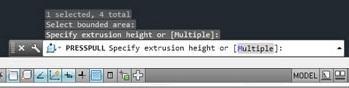
PressPull
PressPull is more flexible and context sensitive. Use PressPull on multiple objects at one time. PressPull can select 2D and 3D curves (not just inside a bounded area).
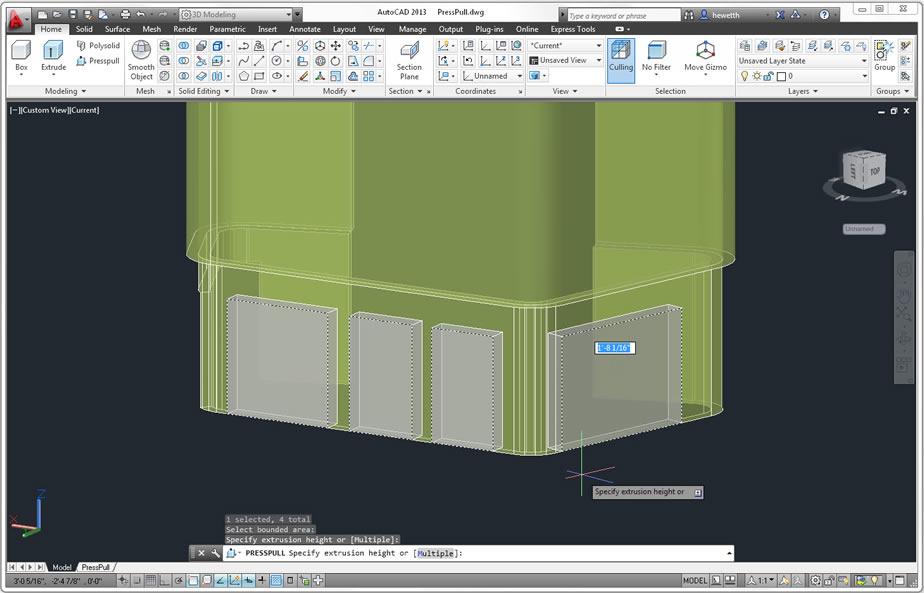
You can use the new Multiple option or the Shift key to press or pull multiple objects in a single operation.
When selecting a face with the Presspull tool, the default behavior extrudes the face straight out. If you press the Ctrl key when you select a planar face, you can offset it as it extrudes to follow the taper angles of adjacent sides.
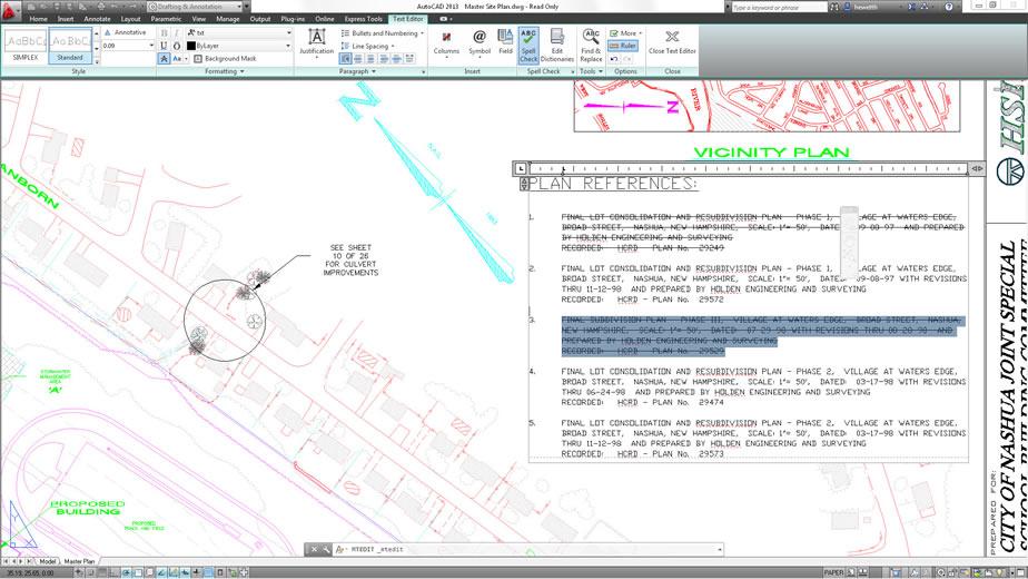
Strike-through Text
Strike-through style is available for Mtext, Mleaders, Dimensions and Tables.
Font Lists
The number of display rows for the Font drop-down list has been increased in the Text Style dialog, the Text Editor ribbon tab, and the ArcAlignedText dialog.
Bring Leaders to the Front
Leaders are now included with the TextToFront tool.
The Mleader text box has been updated to include a margin between the text and the frame and to provide a minimum width for the mtext in order to prevent text overflow.
Wipeout Frame
Control displaying but not plotting the wipeout frame with the new WIPEOUTFRAME system variable.
Reverse Polyline Widths
The new PLINEREVERSEWIDTHS system variable allow more control when using the REVERSE tool to ensure the results you want.
Offset Preview
When using the Offset command, a preview of the offset result is automatically displayed before ending the command.
Snap Behavior
A new Legacy option in the Snap tool offers increased flexibility when snapping to grid points. If Snap Legacy mode is set to yes, the cursor snaps based on the snap spacing, regardless of whether you’re in a command, specifying points, or selecting objects.
When Legacy is set to no, the cursor snaps based on the snap spacing only when specifying points within a command. The snap spacing is ignored when no command is active and when selecting objects within a command.
External References
External Reference functionality has been updated. Now you can edit the Saved Path directly in the External References palette and the Found path is displayed as read-only. The right-click menu includes some additional updates. In the dialog boxes, the default type is set to Relative Path unless the relative path is not available—for example, if the drawing has not yet been saved or the host drawing and external file are located in different disk partitions.
Export Layout
The Export Layout to Model tool has been updated so when you export a layout with drawing views containing circular objects, those objects are represented in the exported drawing as circles and arcs instead of polylines.
Double-click Actions
In the Customize User Interface dialog box, the double-click action for dimension objects has been updated to launch TEXTEDIT rather than the alias TEDIT.
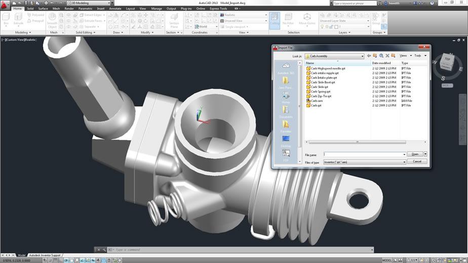
Inventor Import
Inventor Fusion makes it possible to import and edit Inventor models.
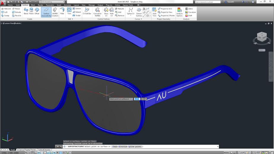
Surface Curve Extraction
Extract Isolines tool is new on the Surface ribbon tab.
Extract isoline curves from an existing surface or face of a solid.
The direction of the isolines can be changed, select a chain or draw a spline on the curved surface.
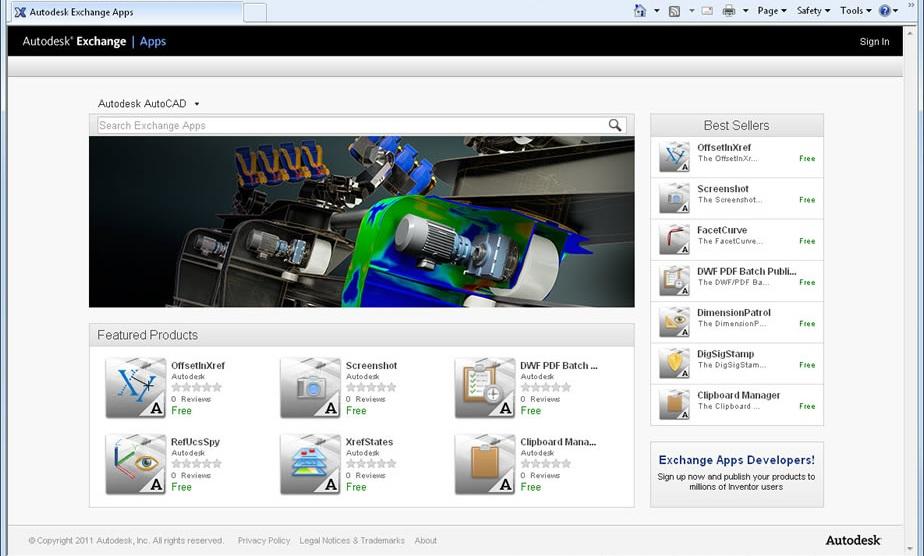
Autodesk Exchange Apps
Apps on Autodesk Exchange can now be accessed from any web browser.
http://apps.exchange.autodesk.com is the URL.
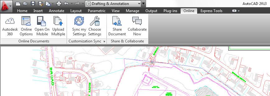
Cloud Connectivity
Online Documents: Autodesk 360, Online Options, Open On Mobile, Upload Multiple
Customization Sync: Sync my Settings, Choose Settings
Share & Collaborate: Share Document, Collaborate Now
In AutoCAD 2013 you can easily connect to your Autodesk 360 account for file sharing, customized file syncing, and more. Sign in directly from the InfoCenter toolbar using your Autodesk single sign-on name and password. If you do not yet have an account, you can create one.
After signing in, your user name and additional tools are displayed in the drop-down menu, including the option to sync your settings with the cloud, specify online options, access Autodesk 360, sign out, and manage account details.
The first time you access Autodesk 360, you have the opportunity to specify default cloud settings to control when your design data and custom settings are synced with the cloud. You can choose to automatically store encrypted copies of your local design data in your Autodesk 360 account each time you save, or save only specified documents. In either case, you can override the default behavior for individual drawings. When you upload drawings directly from AutoCAD to Autodesk 360, external references and other dependent files are automatically included with the upload.
You can also choose to automatically sync your program appearance, profiles, workspaces, options, and support files so that you can restore them on any computer. If you wish to modify the default cloud settings after closing the dialog box, you can access them via Online Options in the drop-down menu and the Online ribbon tab.
Additional tools for working with Autodesk 360 functionality are available in the Online ribbon tab.
The new Autodesk 360 tool opens your Autodesk 360 documents list and folders in a browser. If you are not already logged in, you’re prompted to do so.
Your Autodesk 360 documents are also available from many Select File dialog boxes throughout AutoCAD. For example, when you open, save, or attach a file, you can access Autodesk 360 directly from the Places list on the left side of the dialog box.
The Online Options tool provides easy access to the Online tab in the Options dialog box where you can monitor your online storage capacity and control interaction with cloud documents and customization synchronization. An option in the lower left corner of the dialog box enables you to specify the cloud folder in which you want your drawings to be saved.
The Open on Mobile tool sends a push notification to any mobile device that has AutoCAD® WS software installed and where you are signed in with the same Autodesk ID. The push notification will enable you to open up the current drawing on your mobile without having to browse to the file or open AutoCAD WS first.
The Upload Multiple tool enables you to browse and select multiple drawings to upload to your Autodesk 360 documents.
Customization synchronization enables you to take advantage of your custom AutoCAD preferences and support files even when you work across multiple machines.
The Sync my Settings tool enables you to start and stop syncing of your custom settings. If you stop syncing your custom settings, your online settings are preserved but no longer updated.
If you choose to sync your settings, AutoCAD compares your local settings with your cloud settings and prompts you to choose whether you want to use your local settings, in which case it will upload them to the cloud, or your online settings, in which case it will download them from the cloud.
Bubble notifications indicate when settings are being uploaded to or downloaded from the cloud.
Use the Choose Settings tool to specify which settings to include in customization sync. These can include: options; customization files; printer support files; custom hatch patterns; custom fonts, shapes, and linetypes; tool palettes; and drawing templates.
The Options setting includes almost all the controls in the Options dialog box.
· The Customization setting includes .cuix, mnu, workspace files, and more.
· The Printer support files setting includes copies of printer support files such as .pc3, ctb, and .stb files.
· The Custom hatch pattern setting includes your custom hatch pattern files.
37
· The Tool Palettes setting includes tool palette files and groups (.atc, .aws).
· The Custom fonts, shapes, and linetypes setting requires the AutoCAD application to be restarted.
When you make changes to your customization settings with synchronization enabled, a bubble notification in the upper right corner notifies you that the changes are being uploaded.
When you sign out of Autodesk 360, a dialog box enables you to choose if you want to keep your custom settings or restore the previous settings.
Use the Share Document tool to easily share the current drawing with other users. If the current drawing is saved locally only, a copy of the drawing is uploaded to the cloud and shared. If an online copy of the drawing already exists, then it is shared. You can control the access level of shared documents.
The Collaborate Now tool will launch AutoCAD WS in the user’s default browser and initiate a collaboration session with another WS user.
The CAD Manager Control Utility is updated to include controls for Autodesk 360. You can install the CAD Manager Control Utility from the Install Tools & Utilities option of the AutoCAD Installer. The new Online tab in the CAD Manager Control Utility enables CAD managers to control their users’ access to Autodesk 360 documents and customization synchronization.
Render Online
New Online Rendering tools enable you to render your 3D AutoCAD models in the cloud using the Autodesk rendering service. Materials are assigned, lights and the environment are set up, and you are ready to create a high-res rendering of four different views of the model. The views are sent to the cloud for rendering while you continue to work on your computer; you’re notified when the renderings are ready.
Browse your online render gallery.
You can access the Online Rendering tools from the Render ribbon tab.
Content Explorer
The AutoCAD® Content Explorer functionality, which is accessible from the Plug-ins ribbon tab, has been updated in AutoCAD 2013. New capabilities include basic indexing support (file name, date created, etc.) for many more file types. Any file that can be opened, imported, and attached using AutoCAD is now included in the index and will be returned as search results. For example, you can search for raster images and PDF files by name and then attach them to the open drawing. The filter dialog enables you to choose which file types to include in your search.
The search algorithms have also been improved to support more intuitive search input—especially for wildcard (*) searches. These improvements help produce more accurate search results. Many of these improvements were added in response to feedback from customers and tested against their examples.
In AutoCAD 2012, you were able to connect to server machines that had the Content Service installed, in order to quickly search for files/objects across large library folders. This connection capability has been extended in AutoCAD 2013 to include ANY computer that has the Content Service installed. Therefore, you can connect to your colleague’s watched folders and search their content for peer-to-peer file and object sharing—but only if they’ve explicitly granted access to the folder (Windows®-based security and firewall security still apply).
Language Packs
New Language Packs in AutoCAD 2013 help simplify the process of downloading and using multiple languages in AutoCAD. Now, rather than installing a full version of AutoCAD for each language, you install one full product and then add subsequent languages via Language Packs, resulting in smaller download and install time and space for the secondary languages.
You can download Language Packs from the Help menu in the upper right corner of the application.
A launch icon and menu item for each installed Language Pack is added to the Windows desktop and Start menu.
Language switching is performed with the undocumented parameter or command line switch "/language" for acad.exe.
Languages available for AutoCAD 2013: English, Brazilian Portuguese, Czech, French, German, Hungarian, Italian, Korean, Polish, Russian, Simplified Chinese, Spanish and Traditional Chinese.
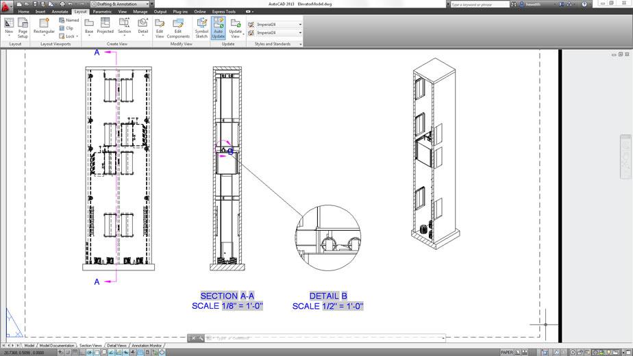
Model Documentation
Detail Views and Section Views has been added.
It is now possible to select what objects to include in the model documentation.
Dimensions added to the drawing views (with the model documentation tools) are associative.
The Base View tool includes a new Select option that enables you to specify which 3D objects are represented in the base view. The Select option is also available when editing the base view after it’s been created. When using the Select option, AutoCAD temporarily switches to model space, enabling you to add or remove objects for the base view selection set.
You can also start in Model Space and select the objects for which you want to create a view. Then, using the Base View tool, choose From Model Space. You can specify the name of an existing layout or enter a new layout name. AutoCAD automatically creates the new layout if necessary and makes it active.
When you create drawing views using the model documentation tools in AutoCAD, relevant layers with an MD_ prefix are automatically added to the drawing. If you rename the layers or change layer properties, those changes are automatically applied to existing as well as subsequent drawing views created in the same drawing.
Create a section view from an existing drawing view by picking points to define the section line. A context-sensitive ribbon tab provides easy access to Section View Creation tools, including depth and hatch controls.
A section identifier is automatically applied and incremented as you create subsequent section views, or you can override it with your own identifier. You can also choose to display a view label identifying the section and scale.
You can control whether individual model components participate in the section using the Edit Components tool on the Layout ribbon tab. If the selected components are set to None, the components display without being sectioned. The participation of components is passed to child views projected from the section view.
You can also specify if the section view should include the full depth or just a slice.
The appearance of the section view label is determined by the Section View Style tool, which is accessible from the Model Documentation ribbon tab. You can select from predefined Section View Styles or define your own using the Section View Style Manager.
In the Section View Style Manager, you can create new section view styles as well as modify or delete existing ones.
When creating or modifying a section view style you have access to a variety of controls to specify the appearance of the section identifier and arrows, cutting plane, view label, and hatch.
You can easily modify a section view after it’s been created. Multifunctional grips on the section line enable you to move the section line, add and remove vertices, flip the direction, and reposition the identifiers.
Grips on the section view and section view label enable you to modify the view position or scale as well as change the label location, width, and height. If the section view includes hatches, you can edit properties of the hatch pattern using a multifunctional grip. It still remains associated with the section view.
Additional editing tools are available in the Section View Editor, which is accessible from the right-click menu and the ribbon tab (Edit View/VIEWEDIT button) when a section view is selected.
Create detail views from existing drawing views. A context-sensitive ribbon tab provides easy access to Detail View Creation tools, which enable you to specify a circular or rectangular boundary, control whether the boundary is displayed, and choose smooth or jagged edges.
A detail identifier is automatically applied and incremented as you create subsequent detail views, or you can override it with your own identifier. A view label identifying the detail view and scale is automatically inserted.
The appearance of the detail view label is determined by the Detail View Style tool, which is accessible from the Model Documentation ribbon tab. You can select from predefined detail view styles or define your own using the Detail View Style Manager.
In the Detail View Style Manager, you can create new detail view styles as well as modify or delete existing ones.
When creating or modifying a detail view style you can specify a variety of options to control the detail boundary, view label, and detail view.
You can easily modify a detail view after it’s been created. Grips on the detail symbol enable you to modify the position of the boundary and the identifier.
Grips on the detail view and detail view label enable you to modify the view position or scale as well as change the label location, width, and height.
Additional editing tools are available in the Detail View Editor, which you can access via the right-click menu and ribbon tab when a detail view is selected.
View Symbol Sketch
Use the Symbol Sketch tool to constrain section lines and detail boundaries to key points in the drawing views, helping maintain accuracy even as the model or layout changes.
Associative Annotations
Regardless of which types of drawing views you create—base, projected, section or detail—you can add associated annotations using traditional dimensioning and multileader tools. The annotations are associated to the drawing view based on the vertices selected or inferred by the selected edge. As a result, if you transform (move, rotate, scale) or update the drawing view, the annotations react accordingly. For example, if you move the drawing view, associative annotations move with it even if they were not included in the move selection set. If you update the drawing view, associative annotations remain associated to the vertices as the geometry changes in size. You can make other edits to the drawing views, such as changing the view style, object visibility, and adding or removing objects to the view selection set, while still maintaining associativity with annotations.
Since the annotations are associated to the drawing view and the drawing view is associated to the model, it’s possible for edits to the drawing view or model to invalidate, or disassociate, annotations. For example, if you delete a drawing view that has associative annotations or you delete part of a model that has been annotated in the drawing view, the associated annotations are meaningless. The new Annotation Monitor in AutoCAD 2013 helps you identify and address those disassociated annotations.
An Annotation Monitor button is included on the AutoCAD status bar. When turned on, it provides feedback regarding the state of associative annotations. If all annotations in the current drawing are associated, the annotation icon in the system tray remains normal.
As soon as at least one annotation becomes disassociated, the annotation monitor icon in the system tray changes and alert badges are displayed on each of the disassociated annotations in the drawing. You can click on individual annotations to reassociate or delete them one at a time or select the link in the Annotation Monitor alert bubble to quickly delete all of the disassociated annotations.
Automatic View Update
The Auto Update tool controls whether drawing views are updated automatically when the source model changes.
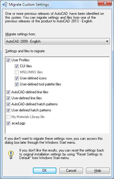
Migration
Template updated
The template has been updated.
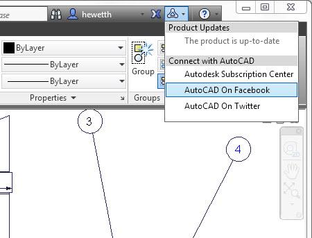
Social Media Links
New tools in the InfoCenter make it easy for you to stay connected with the AutoCAD community. Access the Stay Connected menu, where you can download product updates, log onto the Autodesk® Subscription Center, view the AutoCAD Facebook page, and follow AutoCAD Twitter posts.
Deployment/setup
The deployment builder is more streamlined and easy to use than the 2012 products. The deployment includes a script template for use with Microsoft System Center Configuration Manager 2007.
If you install multiple AutoCAD verticals as well as different languages you will find that they install into the same location and sharing what can be shared, saving hard disk space for you. To start AutoCAD Architecture this command line is used:
"C:\Program Files\Autodesk\AutoCAD 2013\acad.exe" /ld "C:\Program Files\Autodesk\AutoCAD 2013\AecBase.dbx" /p "" /product "ACA" /language "en-US"
Note the new undocumented command line switches /product and /language. With AutoCAD 2013, Architecture, MEP, Mechanical, AutoCAD Structural Detailing all install to the same folder. The /product switch governs which program loads, since the same acad.exe is used for all of them. The text for the switch is ACAD, ACA, MEP, ACADM or ASD. Other products like AutoCAD Map 3D installs into their own folder.
Installed products can be found in the registry at this location:
HKEY_LOCAL_MACHINE\SOFTWARE\Autodesk\AutoCAD\R19.0\InstalledProducts
API and more for Programmers
There is a break in binary compatibility for .NET applications in AutoCAD 2013. It's needed to include a project reference to AcCoreMgd.dll (in addition to AcMgd.dll and AcDbMgd.dll). There have also been namespace changes.
.NET Framework 4 needs to be targeted in Visual Studio.
Autodesk.AutoCAD.DatabaseServices.ObjectId supports dynamic operations. This means that you can declare an ObjectId using the dynamic keyword in C#, and you can then choose to access any of the properties or methods exposed by the object possessing that ID directly from the ObjectId itself. The ObjectId then takes care of the open & close operations implicitly, so there’s no need to mess around with transactions, etc. ref
Language switching with new command line switch
Install the language package and then the command line switch /language "en-US" can be modified to for example /language "zh-CN" for Simplified Chinese.
AutoCAD Core Console is big news. Now it's possible to run AutoCAD without GUI overhead. The command-line only UI, AcCoreConsole.exe is only 24 KB. The console can load DBX modules – which are coded against ObjectDBX/RealDWG, CRX modules and .NET DLLs that have been coded against the new AcCoreMgd.dll (rather than AcMgd.dll). Even AutoLISP (Visual LISP) and SCR (script files) can be loaded but without GUI features. ref
SmartPurger has been updated to support the Core Console.
When AcCoreConsole.exe is run this will show on the command line:
AutoCAD Core Engine Console - Copyright Autodesk, Inc 2009-2011.
Usage:
AcCoreConsole.exe [/i <input dwg>] /s <script> [/l <language>] [/isolate <userid
>]
Example:
AcCoreConsole.exe /i 8th_floor.dwg /s test.scr /l en-US
Command:
And then commands can be entered on the command line.
The AcCoreConsole.exe command line switches explained:
1) /i : Used to specify the drawing file path on which to run the script file
2) /s : Used to specify the path to the script file.
3) /l : If language packs are installed, you have the choice to invoke the language version of accoreconsole. The commands in the script file can then be in one of the languages that you have installed in your system.
4) /isolate : Used to prevent the changes to the system variables from affecting regular AutoCAD.
Model Documentation API got read-only access via classes isSectionSymbol, SectionViewstyle, ViewBorder, ViewRepBlockReference, DetailViewStyle and DetailSymbol. ref
Non-COM Properties C++-only improvements related to Properties Window and more.
Autoloader updates
- Support for F1 context-sensitive help integration
- The ability to add tool-palette support paths
- Demand-loading on command invocation for AutoLISP applications
- The option to specify a command to be called when an application is loaded
DCL and Unicode
DCL files by default are saved in ANSI format where the characters depend on the code page being used. In previous versions the character set selection when dispaying the DCL dialogs was based on the OS settings, whereas in the new version it is based on the language version of AutoCAD. To make your DCL file use the UTF-8 format, simply open it in Notepad, then in the Save As dialog setEncoding to UTF-8. Note that Visual Lisp editor doesn't show UTF-8 files properly, so you'll have to edit those in a unicode compatible editor such as Notepad.
AutoCAD 2013 ActiveX API News
A full list of the changes made to the AutoCAD 2013 ActiveX API are:
Changed Enums:
AcSaveAsType
ac2013_dwg = 60 (New)
ac2013_dxf = 61 (New)
ac2013_Template = 62 (New)
acNative = 60 (Changed)
New Enums:
AcPointCloudIntensityStyle
acIntensityGrayscale = 0
acIntensityRainbow = 1
acIntensityRed = 2
acIntensityGreen = 3
acIntensityBlue = 4
acIntensityEditableFlag = 5
AcPointCloudColorType
acTrueColor = 0
acByColor = 1
Changed Classes:
IAcad3DSolid
CheckInterference - Method (Added solid interfere parameter)
IAcadDynamicBlockReferenceProperty (Changed)
show - Property (Renamed, previously Show)
IAcadEntity
EntityTransparency - Property (New)
IAcadHatch
BackgroundColor - Property (New)
IAcadLoftedSurface
EndSmoothContinuity - Property (New)
EndSmoothMagnitude - Property (New)
Periodic - Property
StartSmoothContinuity - Property (New)
StartSmoothMagnitude - Property (New)
IAcadPointCloud
Height - Property (New)
IntensityColorScheme - Property (New)
Length - Property (New)
Name - Property (New)
Path - Property (New)
ShowClipped - Property (New)
ShowIntensity - Property (New)
Width - Property (New)
IAcadPreferencesFiles
ActiveInvProject - Property (New)
IAcadRasterImage
transparency - Property (Renamed, previously Transparency)
IAcadSpline
Closed2 - Property (New)
Degree2 - Property (New)
KnotParameterization - Property (New)
SplineFrame - Property (New)
SplineMethod - Property (New)
IAcadSurface
EdgeExtensionDistances - Property (New)
MaintainAssociativity - Property (New)
ShowAssociativity - Property (New)
SurfTrimAssociativity - Property (New)
WireframeType - Property (New)
Removed Classes:
Classes were merged with the class in which they were derived in most cases (ie. IAcadEntity2 -> IAcadEntity)
IAcad3DFace2
IAcad3DPolyline2
IAcad3DSolid2
IAcadArc2
IAcadAttribute2
IAcadBlockReference2
IAcadCircle2
IAcadDim3PointAngular2
IAcadDimAligned2
IAcadDimAngular2
IAcadDimArcLength2
IAcadDimDiametric2
IAcadDimOrdinate2
IAcadDimRadial2
IAcadDimRadialLarge2
IAcadDimRotated2
IAcadEllipse2
IAcadEntity2
IAcadExternalReference2
IAcadExtrudedSurface2
IAcadExtrudedSurface3
IAcadHatch2
IAcadHelix2
IAcadLine2
IAcadLeader2
IAcadLoftedSurface2
IAcadLoftedSurface3
IAcadLWPolyline2
IAcadMLeader2
IAcadMText2
IAcadNurbSurface2
IAcadOle2
IAcadPlaneSurface2
IAcadPlaneSurface3
IAcadPoint2
IAcadPolyfaceMesh2
IAcadPolygonMesh2
IAcadPolyline2
IAcadPViewport2
IAcadRay2
IAcadRasterImage2
IAcadRegion2
IAcadRevolvedSurface2
IAcadRevolvedSurface3
IAcadShape2
IAcadSolid2
IAcadSpline2
IAcadSurface2
IAcadSurface3
IAcadSweptSurface2
IAcadSweptSurface3
IAcadSubDMesh2
IAcadTable2
IAcadText2
IAcadTolerance2
IAcadTrace2
IAcadXline2
IAcadWipeout2
Visual LISP
There were a few additions to the Visual LISP extension in AutoCAD 2013 which expose some new functionality from the ActiveX API and a few new functions that allow you to obtain the Machine and User product keys of AutoCAD. Along with some new functions, there are some new variables introduced as a result of new constants being added to the ActiveX API.
To use the the changes made to the Visual LISP extension, be sure to call the VL-LOAD-COM function first.
New Functions:
VLA-GET-ACTIVEINVPROJECT / VLA-PUT-ACTIVEINVPROJECT - Specifies the active Inventor project being used by the Model Documentation feature. (Internal Use Only)
VLA-GET-INTENSITYCOLORSCHEME / VLA-PUT-INTENSITYCOLORSCHEME - Specifies the color scheme to use for displaying intensity values.
VLA-GET-SHOWCLIPPED / VLA-PUT-SHOWCLIPPED - Enables or disables the clipping boundary.
VLA-GET-SHOWINTENSITY / VLA-PUT-SHOWINTENSITY - Specifies if the point cloud is displayed using a shaded color scheme.
VLA-PUT-LENGTH - Sets the Length property for a point cloud.
VLAX-MACHINE-PRODUCT-KEY - Returns the AutoCAD product key from the Machine hive in the Windows Registry. (ie. "Software\\Autodesk\\AutoCAD\\R19.0\\ACAD-B001:409")
VLAX-USER-PRODUCT-KEY - Returns the AutoCAD product keyfrom the User hive in the Windows Registry. (ie. "Software\\Autodesk\\AutoCAD\\R19.0\\ACAD-B001:409")
Changed Variables:
ACNATIVE = 60
New Variables:
AC2013_DWG = 60
AC2013_DXF = 61
AC2013_TEMPLATE = 62
ACINTENSITYBLUE = 4
ACINTENSITYEDITABLEFLAG = 5
ACINTENSITYGRAYSCALE = 0
ACINTENSITYGREEN = 3
ACINTENSITYRAINBOW = 1
ACINTENSITYRED = 2
ACTRUECOLOR = 0
VBA for AutoCAD
VBA (Microsoft Visual Basic for Applications) is still available in AutoCAD 2013 but it is not included with the installation media. Find the VBA for AutoCAD downloads here at http://www.autodesk.com/vba-download. As VBA probably will not be around for future versions consider converting your existing VBA code to C# or VB.NET and if you like help with it please feel free to contact us.
UPDATE: As of January 31, 2014, Autodesk is no longer authorized to distribute VBA 6 or earlier versions of VBA for use with Autodesk AutoCAD and other Autodesk products. This change affects the availability to download and install VBA for Autodesk AutoCAD 2013 or earlier.
AutoCAD 2013 System requirements
Note that Windows Vista is not supported by Autodesk for AutoCAD 2013. Autodesk to cease support of Windows Vista even though Microsoft changed their mind Autodesk didn’t follow. With SP2 also Windows 8 is supported.
There is nothing that restricts you from running AutoCAD 2013 on Windows Vista but you're on your own. Other than that if you already run AutoCAD 2011 or AutoCAD 2012 your system will probably work the same.
As always with system requirements these are minimal requirements for AutoCAD to run. For professional usage you surely want to have much better hardware.
FlexNet version 11.10.0.3 for Autodesk Network License Manager.
32-bit version
Operating System:
- Service Pack 3 (SP3) or later of the following:
- Microsoft Windows XP Professional
- Microsoft Windows XP Home
- The following operating systems:
- Microsoft Windows 7 Enterprise
- Microsoft Windows 7 Ultimate
- Microsoft Windows 7 Professional
- Microsoft Windows 7 Home Premium
Hardware:
- CPU
- Memory: 2 GB (4 GB recommended)
- Disk: Installation requires 6 GB space
- Display: 1,024 x 768 with true color (1,600 x 1,050 with true color recommended)
Misc.
- Browser: Internet Explorer 7.0 or later web browser
- File Formats: (New file format in AutoCAD 2013):
- Save-as Support
AutoCAD R14, AutoCAD 2000, AutoCAD 2004, AutoCAD 2007, AutoCAD 2010, AutoCAD 2013. - DXF Support
AutoCAD R12, AutoCAD 2000, AutoCAD 2004, AutoCAD 2007, AutoCAD 2010, AutoCAD 2013
- Save-as Support
- API
- LISP are compatible
- Scripts are compatible
- ObjectARX application will need to be recompiled
64-bit version
Operating System:
- Service Pack 2 (SP2) or later of the following:
- Microsoft Windows XP Professional
- The following operating systems:
- Microsoft Windows 7 Enterprise
- Microsoft Windows 7 Ultimate
- Microsoft Windows 7 Professional
- Microsoft Windows 7 Home Premium
Hardware:
- CPU
- Memory: 2 GB (4 GB recommended)
- Disk: Installation requires 6 GB space
- Display: 1,024 x 768 with true color (1,600 x 1,050 with true color recommended)
For both 32 & 64-bit Misc.
- Browser: Internet Explorer 7.0 or later web browser
- File Formats: (New file format in AutoCAD 2013):
- Save-as Support AutoCAD R14, AutoCAD 2000, AutoCAD 2004, AutoCAD 2007, AutoCAD 2010, AutoCAD 2013.
- DXF Support AutoCAD R12, AutoCAD 2000, AutoCAD 2004, AutoCAD 2007, AutoCAD 2010, AutoCAD 2013
- API
- LISP are compatible
- Scripts are compatible
- ObjectARX application will need to be recompiled
For both 32 & 64-bit using 3D modeling workflows:
- Memory 4 GB RAM or more
- 6 GB free hard disk available not including installation requirements
- 1,280 x 1,024 True color video display adapter 128 MB or greater, Pixel Shader 3.0 or greater support by your graphics card, Direct3D capable workstation class graphics card.
Still missing
Still missing. Wish list for the next time.
Using fence it would be possible to select an object with a linetype with spaces when the fence is hitting the space in the linetype.
Preview handlerfor Vista and Outlook 2007 and Outlook 2010.
In sheet set manager it used to work adding the Unicode \U+000A to force a new line (line feed) in properties so it showed on say two lines on the drawing. Now it gives a new line using SHX fonts and nothing at all with TTF fonts.
Add support to find solid and gradient hatches with the Matchprop command as easily as you can with the Erase command and solid hatches.
If you have a select object command like Erase and move it over a solid or gradhatch it is not always showing that the object is selectable (selection preview) even though it is if you try to click on it.
In dialog boxes like the Open dialog box it should be possible to save changes like columns to show, width, sorting, grouping etc.
Ability to change background color and size of DWG previews in for example the Open dialog box.
Be able to rotate OLE objects.
Easy way to change the length of the extension lines on dimensions.
Improve the functionality to show real symbols for mtext and also delete any that are not used. It is now only possible to add new ones through the registry. Personal Mtext Symbols.
Having the help window linked to the main application window is not always wanted. Give us a better option.
Make the help search functionality more relevant. Try to search for LINE and you see the problem.
Add some kind of table of contents to the help system. By functionality, by command, variable, etc.
Existing bugs
Existing bugs, defects, feature limitation or other issues.
When creating a new sheet in Sheet Set Manager the create date attribute on the file is inherited from the Sheet template. AutoCAD should use the date/time when the sheet is created instead.
Drawing Revision number as seen in DWGPROPS is used when adding a Sheet List Table and there is no way to show the sheet property Revision number. Revision date, Purpose and Category cannot be added to the table either.
Tips & Tricks
Tips & Tricks
AutoCAD 2013 also is referred to as ACAD2013 or ACAD 2013.
AutoCAD 2013 product keys is 001E1.
_VERNUM (product version) details:
AutoCAD 2013 SP2: G.204.0.0 (UNICODE)
AutoCAD 2013 SP1.1: G.114.0.0 (UNICODE)
AutoCAD 2013 SP1: G.112.0.0 (UNICODE)
AutoCAD 2013: G.55.0.0 (UNICODE)
Readme
Readme
Product Help:
Product Help is available online and is not installed with the product by default. You can launch the Help installation at the end of the product installation, or after launching the product by selecting Download Offline Help from the Help icon.
Welcome Screen:
Adobe Flash Player is required to view some video content. It may not install when accessed directly from the Welcome Screen. In this case, please install it directly from the Adobe Flash download page. If prompted to select the Flash Player version to install, be sure to select Flash Player For Other Browsers for best compatibility.
Video Content:
QuickTime is required to view some video content. If videos fail to play, please install it directly from the Apple QuickTime download page.
FAQ
1. General Product Information
1.1 What is AutoCAD 2013 software?
You can design and shape the world around you with the powerful, flexible features
found in AutoCAD software, one of the world’s leading 2D and 3D design software
products. Powerful tools for design aggregation help connect and streamline your
design and documentation workflows. Import and aggregate models from almost any
format, and quickly create detailed design layouts and drawing views that
automatically update when the source model changes. Save time with an enhanced
and more effortless user interface and a customizable Command Line display.
Synchronize your drawings and folders with Autodesk® 360 to access your designs
from almost anywhere. And with a single destination to find and install hundreds of
different Autodesk-approved apps, you can extend the power of your software more
easily than ever before.
1.2 Who uses AutoCAD software?
AutoCAD software is used by architects, CAD technicians, designers,
engineers, project managers, and CAD/IT managers in a variety of
industries, including the manufacturing, building, civil, and mapping
industries.
For example, AutoCAD is used by:
• Design professionals who create conceptual designs, exploring
ideas in 3D models.
• Design professionals who create technical drawings.
• Drafters who put the finishing touches on a design with detailing,
annotations, links to online data, and verification of accuracy.
• Contractors, suppliers, or operational professionals who need to
review drawings to extrapolate data specific to their businesses.
• Principals and project leaders who need to review and edit
drawings and monitor progress.
2. Pricing and How to Buy
2.1 What are the licensing options and pricing for AutoCAD 2013 software?
AutoCAD 2013 software is available through your local reseller, online retailers, or
from the Autodesk Store.
Consult your local reseller or the Autodesk Store for pricing information and for
information on Autodesk® Subscription.
2.2 Can I try AutoCAD 2013 software before I buy it?
Yes, you can try it out by downloading or requesting the AutoCAD 2013 software trial
version. This fully functioning version of AutoCAD 2013 is available as a free* 30-day
trial. You can order the trial DVD (64-bit and 32-bit for Windows) from your Autodesk
Authorized Reseller or simply download the fully functioning trial version.
*Free products are subject to the terms and conditions of the end-user license and services
agreement that accompanies the software.
2.3 What benefits does Autodesk Subscription offer?
Get the benefits of more cloud computing capabilities and capacity,
upgrades to the latest software releases, online technical support, and
flexible licensing privileges with Autodesk Subscription. Get any releases
of AutoCAD software that become available during your subscription term
automatically via download, incremental product enhancements, and
exclusive license terms that are available only to Subscription members.
The annual fee includes these benefits:
• Subscription customers have an advantage with Autodesk 360
cloud-enabled services, including greater cloud computing
capabilities and more storage capacity. As a result, they can view
and share more design files on web or mobile devices, simulate
and visualize more design options, and improve project results
with web-based collaboration and data management solutions.
• Autodesk Subscription offers a way to make your AutoCAD
software costs predictable. Whether you opt for a one-year
subscription or a multiyear contract, the costs are known for the
entire term of your contract.
• Product enhancements may include extensions or other rich
content for AutoCAD software, and these enhancements are
exclusive to Subscription members. Only Subscription members
can access these new product downloads that add new
functionality and/or features to your AutoCAD software. Since
they adapt easily into your current workflows, you can quickly
apply them to your new projects to help you stay competitive.
• Autodesk Subscription makes managing software licensing
hassle-free and flexible. You have added flexibility to allow your
employees to use their AutoCAD software—in the office or at
home. Better yet, designers are entitled to run previous versions
of AutoCAD concurrently with the latest release (under certain
conditions), so updates won’t cause disruptions to ongoing
projects where clients or partners are running previous versions.
Learn more by visiting the Autodesk Subscription product center.
2.4 What product downloads are available for AutoCAD Subscription members?
Product downloads may include any releases of the software, extensions
or bonus packs that become available during your subscription term, or
other rich content for AutoCAD software. These enhancements are
exclusive to Subscription members and can be downloaded from the
Subscription Center.
3. Compatibility and Interoperability
3.1 Do third-party applications based on previous versions of AutoCAD
software work with AutoCAD 2013 software?
Third-party applications built for previous versions of AutoCAD and based
on ActiveX® and ObjectARX® developer tools require upgrades to be
compatible with AutoCAD 2013. Check with your application
developer/supplier regarding availability of applications built for AutoCAD
2013.
3.2 Do AutoCAD 2012 customized menus work in AutoCAD 2013 software?
Yes, AutoCAD 2013 software automatically migrates customized menus
(CUI files). The first time you launch AutoCAD 2013, the migration feature
asks you if you would like to migrate the settings from your previous
AutoCAD version to AutoCAD 2013. The migration feature helps you make
a smooth transition to the new release by automatically migrating
customized menus, toolbar icons, hatch patterns, linetypes, command
shortcuts, and profiles. Refer to Services & Support for additional
migration tools.
3.3 Has the AutoCAD 2013 DWG file format changed from the AutoCAD
2012 product?
AutoCAD 2013 software introduces an updated file format to
accommodate technology and performance improvements in the software.
AutoCAD 2013 enables you to save drawings in a wide variety of other
formats, ranging back to R14 DWG TM and R12 DXF TM formats.
3.4 Does AutoCAD 2013 software read and save drawings created by
earlier releases of AutoCAD?
AutoCAD 2013 reads drawing files from all previous versions of AutoCAD
software. AutoCAD 2013 has a built-in Save As function, so you can save
drawings to and from AutoCAD releases using the AutoCAD Release 14,
2000, 2004, 2007, and 2010 DWG formats. In addition, you can use the
SaveAs AutoCAD Release 12 DXF command to support releases prior to
AutoCAD Release 14.
3.5 Can I open an AutoCAD 2013 drawing with an older release of AutoCAD?
In order to open AutoCAD 2013 drawings with older releases of AutoCAD,
you should use Autodesk® DWG TrueView™ software to translate DWG
files to AutoCAD Release 14, 2000, 2004, 2007, and 2010 file formats.
DWG TrueView can be downloaded at www.autodesk.com/dwgtrueview.
DWG TrueView does not require the AutoCAD application in order to
convert DWG files.
3.6 Can I run AutoCAD 2013 side-by-side with other AutoCAD platform–based
applications?
Yes, AutoCAD 2013 can be installed side-by-side with any other AutoCAD
or Autodesk vertical solution, including AutoCAD 2012–based products.
3.7 Is AutoCAD 2013 compatible with AutoCAD LT?
Yes, AutoCAD 2013 is fully DWG-compatible with AutoCAD LT 2013
software. It can read files from all older versions of AutoCAD LT and can
save to the AutoCAD 2010, 2007, 2004, 2000, and Release 14 DWG file
formats for compatibility with older products.
4. Platform and System Requirements
4.1 What are the system requirements for AutoCAD 2013 software?
System requirements can be found online.
4.2 Does AutoCAD 2013 software support 64-bit operating systems?
Yes. See the system requirements above.
4.3 Does AutoCAD 2013 software support Windows Vista?
No, AutoCAD 2013 does not support the Windows Vista® operating system.
4.4 Does AutoCAD 2013 software support Mac OS X?
AutoCAD 2013 for Mac supports some versions of Mac OS® X. See the system
requirements above.
4.5 What are the differences between AutoCAD 2013 and AutoCAD 2013 for
Mac?
AutoCAD 2013 and AutoCAD 2013 for Mac are based on much of the same source
code; however, AutoCAD for Mac 2013 has a look and feel that is familiar to users of
other Mac software. Please refer to the AutoCAD 2013 Platform Comparison Matrix.
4.6 Does AutoCAD 2013 software support multiple CPU systems?
Yes, AutoCAD 2013 software supports multiple CPUs. The performance of AutoCAD
graphics and rendering systems benefits from multiple CPU systems.
5. Licensing
5.1 What is product activation?
Product activation is a software-based license management technology
incorporated into many Autodesk products. It is a secure and trouble-free
process that authenticates licensed users running Autodesk software. The
process verifies that the serial number is legitimate and is activated only
on eligible computers. It does not affect the ability of licensed users to
operate their software the way they have always done.
5.2 How do I activate my software?
The first time you start up the product, you can activate your product 24
hours a day, seven days a week, over the Internet or via email. Either
option takes only a few steps to complete and requires your product serial
number and registration information.
5.3 What if I have more than one computer? Will product activation allow me to
use the software on multiple machines?
Autodesk recognizes that some users may need to operate the software
when they are away from their usual work location. To accommodate this
need, the product activation technology allows an employee to install the
software on a second computer owned by the employee’s company,
provided it is for use away from the employee’s usual work location, the
software is used only by that employee and no other, and only one of the
two copies of the software is ever in use at any one time. Consult the
Autodesk Software License Agreement for details about using the software
on a second computer.
5.4 What if I use a PC and a Mac? Will product activation allow me to use the
software on separate machines on different operating systems?
If you have purchased a license of AutoCAD 2013 or AutoCAD 2013 for
Mac you are entitled to cross-licensing options that allow you to activate
either Windows or Mac OS X versions of your software. AutoCAD 2013
can be installed and activated on Windows or Mac OS X with the same
serial number and product keys two times in a 12-month period, provided
that you are compliant with the policy listed in section 5.3. The two
activations can either be two Windows activations, two Mac OS X
activations, or one Windows activation plus one Mac OS X activation. Get
more information on cross-platform licensing.
5.5 How do I transfer my software license to another machine?
The Online License Transfer (OLT) Utility allows licenses to be moved
between machines. The OLT replaces the former Portable License Utility.
To transfer a license, simply start the transfer utility and choose Export.
Then log in to the OLT website and “park” your license at an Autodesk
“parking area.” At the destination computer, start the transfer utility and
choose Import. Log back in to the OLT website and import your license to
the destination computer.
5.6 Where can I find more information about software activation?
More information on product activation can be found online.
6. Support and Training
6.1 How do I obtain direct technical support?
Direct technical support is available from both Autodesk and Autodesk
Authorized Resellers.
Furthermore, Autodesk Subscription is a comprehensive software,
support, and training package that simplifies your technology upgrades
and boosts your design productivity. Purchase of Autodesk Subscription
includes web support from Autodesk technical experts for all your
installation, configuration, and troubleshooting questions.
To learn more about Autodesk Subscription, contact your Autodesk
Account Executive or your Autodesk Authorized Reseller, or visit the
Subscription Center.
Find a complete list of support options for AutoCAD on the Autodesk
website.
6.2 How can I get personalized support and training for AutoCAD 2013
software?
If you purchased this product from an Autodesk Authorized Reseller,
contact your reseller for support and training information. To locate an
Autodesk Authorized Reseller in your area, call your local Autodesk office
or visit the Autodesk website.
Find a complete list of support options for AutoCAD on the Autodesk
website.
6.3 Where do I find training courses for AutoCAD 2013 software?
You can attend instructor-led training at Autodesk Authorized Training
Center (ATC®) locations around the world. These training centers use
Autodesk Official Training Courseware (AOTC) to deliver comprehensive
courses for new and intermediate AutoCAD software users. Autodesk ATC
sites also deliver custom courses on AutoCAD and other Autodesk
products.
6.4 How do I find out if service packs are available for AutoCAD 2013 software?
In the event that Autodesk releases an AutoCAD 2013 software service
pack, it is easy to access and install it using the Autodesk Exchange
feature within the product. Check the Autodesk Exchange window to see if
an update is available. AutoCAD 2013 automatically recognizes if you
have the most up-to-date release and prompts you if there is an update
available. When you click the link, AutoCAD 2013 automatically downloads
and installs the update.
Updates & Service Packs
Updates & Service Packs.
- AutoCAD 2013 Service Pack 2
- Scale List Cleanup Utility for AutoCAD 2013/2014
- Regapp ID Cleanup Utility for AutoCAD 2013/2014
- Autodesk IPv6 Network License Manager for Windows
- Autodesk IPv4 Network License Manager for Windows
- Autodesk MASSPROP Hotfix
- Autodesk SketchBook Designer 2013 SP2
- Autodesk 3Dconnexion Hotfix
- AutoCAD 2013 Service Pack 1.1
- AutoCAD 2013 Service Pack 1
- Hotfix - Persistent Autodesk Sync error in the system tray
- Autodesk Sync 2013 Service Pack 1
- 2013: Autodesk Point Cloud Hotfix
AutoCAD Civil 2013 Object Enabler
…AutoCAD Civil 2013 Object Enabler …you can use to access AutoCAD Civil 3D drawing files. This…allows object data created in AutoCAD Civil 3D 2013 to be…
ID DL19052749
Date: 2012-Apr-18
AutoCAD Plant 3D 2013 Object Enablers
…AutoCAD Plant 3D 2013 Object Enablers…Autodesk software. In particular, the AutoCAD Plant 3D object enabler allows…retrieve property data while reviewing AutoCAD Plant 3D models. …
ID DL19165270
Date: 2012-Apr-17
How to remove all Autodesk products from a Windows system
…product. AutoCAD 2013 installer in Maintenance Mode Click…procedures, e.g., "C:\Program Files\AutoCAD 2010" or "C:\Program Files\Autodesk…2010" or "C:\Program Files\Autodesk\AutoCAD 2012". 2…
ID TS45252
Date: 2012-Apr-17
Online License Transfer FAQs
…2013 and import it into AutoCAD 2013. Similarly, you can't…from one serial number of AutoCAD 2013 and import it into…a different serial number of AutoCAD 2013. …
ID GS19107741
Date: 2012-Apr-16
How to Obtain a Network License File from Autodesk
…so that you can run the NLM. Note: Although the images in this guide show AutoCAD 2012 as an example, the concepts and procedures apply to all Autodesk 2012 (and…
ID GS18275350
Date: 2012-Apr-12
Windows 8 Support for AutoCAD and AutoCAD-based vertical products
…8 Support for AutoCAD and AutoCAD-based vertical products …know if you can run AutoCAD, AutoCAD LT, or AutoCAD-based vertical products on Microsoft…supported operating systems for any AutoCAD versions. The AutoCAD team is investigating compatibility with…
ID TS19048377
Date: 2012-Apr-10
Uninstalling Autodesk Sync
…AutoCAD 2013 and AutoCAD 2013 Vertical Products use Autodesk…will appear in the InfoCenter (AutoCAD and Inventor) or in the…AutoCAD and AutoCAD vertical products …
ID TS18966285
Date: 2012-Apr-09
Open Light 2013 Object Enabler (32-bit and 64-bit)
…this object enabler installed, you can share drawings using proxy graphics representations or the Export to AutoCAD command. Open Light 2013 Object Enabler (32-bit) (exe - 16658Kb) Open Light…
ID DL18986166
Date: 2012-Apr-05
Migration issues may oocur with side by side installations of ACAD 2013 and Vertical ACAD ...
…AutoCAD 2013 is installed on a…on a computer with another AutoCAD 2013 vertical product. When you…Palettes that you need from AutoCAD 2012 to AutoCAD 2013. …
ID TS18845265
Date: 2012-Apr-03
System requirements for AutoCAD
…requirements for AutoCAD …provides the system requirements for AutoCAD Products. …AutoCAD 2013 System Requirements (current version…
ID TS15412189
Date: 2012-Apr-02
AutoCAD Structural Detailing 2013 Object Enablers
…AutoCAD Structural Detailing 2013 Object Enablers…The AutoCAD® Structural Detailing 2013 Object Enabler…allows object data created in AutoCAD Structural Detailing to be accessed…
ID DL18968562
Date: 2012-Mar-30
Optimize Performance within Windows 7 Environments
…notice performance issues with your AutoCAD and AutoCAD vertical problems. …service pack/hotfix for your AutoCAD software. See the following link…the latest update for your AutoCAD product: http://usa.autodesk.com…
ID TS18818398
Date: 2012-Mar-27
2013: Cascading Sequences for Autodesk Products
…AutoCAD 2013 AutoCAD for Mac 2013 AutoCAD Mechanical 2013 AutoCAD P&ID 2013 AutoCAD Plant 3D 2013 AutoCAD Design Suite Standard 2013 Autodesk…AutoCAD for Mac 2013 AutoCAD 2013 AutoCAD Mechanical 2013 AutoCAD P&ID 2013 AutoCAD Plant 3D 2013 AutoCAD Design Suite Standard 2013 Autodesk…AutoCAD LT 2013 AutoCAD LT for Mac 2013 AutoCAD LT Civil Suite 2013 AutoCAD Inventor LT Suite 2013 …
ID TS18708338
Date: 2012-Mar-27
2013: FLEXnet® feature codes for Autodesk products
…AutoCAD 2013 …AutoCAD Architecture 2013 …AutoCAD Civil 3D 2013 …
ID TS18708301
Date: 2012-Mar-27
After Migrating from a previous release, the wrong online Tab is displaying in the Ribbon
…When migrating your settings between AutoCAD 2012 and 2013 The AutoCAD 2013 “Online” Ribbon Tab gets…Tab gets replaced by the AutoCAD WS Ribbon Tab from AutoCAD 2012. The problem is that…Autodesk 360 features in the AutoCAD 2013 “Online” TAB of the…
ID TS18801888
Date: 2012-Mar-27
AutoCAD File Corruption
…AutoCAD File Corruption ID: TS18809891 Issue Your drawing file DWG has become corrupt and slow in…
ID TS18809891
Date: 2012-Mar-27
AutoCAD 2013 DWG file format change
…AutoCAD 2013 DWG file format change…file format was changed in AutoCAD® 2013 and related AutoCAD vertical products and what effect…Since the release of AutoCAD 2010, the DWG file format…
ID TS18801721
Date: 2012-Mar-27
AutoCAD requests to Autodesk servers blocked by proxy servers
…AutoCAD requests to Autodesk servers blocked by…You are using AutoCAD 2012-2013 and notice that…AutoCAD requests to Autodesk servers can…
ID TS16732564
Date: 2012-Mar-27
Activation and Post-Installation Tasks for Autodesk products and suites
…installed with Autodesk products such as Inventor, AutoCAD, Revit, and 3DS Max, among others. There…Enabler If you're using AutoCAD, or an AutoCAD-based vertical product, you may need…
ID TS16883173
Date: 2012-Mar-27
Operating system compatibility for AutoCAD and AutoCAD LT
…for the different releases of AutoCAD® and AutoCAD LT®. …Operating system compatibility for AutoCAD and AutoCAD LT …for the different releases of AutoCAD and AutoCAD LT. …
ID TS14078105
Date: 2012-Mar-27
System requirements for Autodesk 360 Rendering
…0 Google Chrome version 13 System Requirements for Rendering Add-On Revit 2013 System Requirements AutoCAD 2013 System Requirements…
ID TS17807008
Date: 2012-Mar-27
Cursor performance issues in Windows 7 when hardware acceleration is off
…You are running AutoCAD, AutoCAD LT or an AutoCAD-based vertical product in Windows…in Windows 7 and affects AutoCAD LT and all AutoCAD-based products where hardware acceleration…This is done in AutoCAD 2010 and above and AutoCAD LT 2012 and above by…
ID TS14898223
Date: 2012-Mar-16
Flatten 3D model to 2D
…If you are using AutoCAD 2007 and higher, the FLATSHOT…command is not available in AutoCAD LT.) …Model page, under Manufacturers, select AutoCAD DXB File. Under Model, select…
ID TS45483
Date: 2012-Mar-15
Dual monitor configurations
…You want to know if AutoCAD® software supports dual screen (monitor…AutoCAD® does not include any built…a dual monitor configuration with AutoCAD, but the way it works…
ID TS22235
Date: 2012-Mar-15
Autodesk Sync issues when installing a 2013 release product after installing a 2013 beta ...
…the following conditions: You installed AutoCAD Beta 2013 (or Showcase Beta 2013) and subsequently…You installed Inventor Beta 2013 and subsequently install AutoCAD 2013 (or Showcase 2013 ) A couple of…
ID TS18744845
Date: 2012-Mar-13
How to find the product key for your Autodesk product
…For example, a user installing AutoCAD 2012 would use product key…001D1 while a user installing AutoCAD Revit Architecture Suite 2012 (which…Architecture Suite 2012 (which includes AutoCAD 2010) would use product key…
ID TS1105767
Date: 2011-Dec-14
Windows 7 Support for AutoCAD and AutoCAD LT
…7 Support for AutoCAD and AutoCAD LT …to know what versions of AutoCAD® and AutoCAD LT® work with Microsoft Windows…Limitations with Windows 7 for AutoCAD and AutoCAD-based Products …
ID TS14056350
Date: 2011-Nov-24
Educational Plot Stamp Removal Issues
…Student and Faculty) version of AutoCAD or an AutoCAD-based program, the following plot…the educational plot stamp from AutoCAD-based drawings is not supported…educational and student versions of AutoCAD software does not permit using…
ID TS17886605
Date: 2011-Oct-18
Support for AutoCAD® and AutoCAD LT® on Apple computers
…for AutoCAD® and AutoCAD LT® on Apple computers …You want to know if AutoCAD® and AutoCAD LT® are supported on Apple…a Mac-specific version of AutoCAD and AutoCAD LT. More information can be…
ID TS1070248
Date: 2011-Aug-16
AutoCAD 2012 Installation Error 1603, "Error :: Please install DirectX" before installing ...
…AutoCAD 2012 Installation Error 1603, "Error…Please install DirectX" before installing AutoCAD …Run the AutoCAD 2012 setup.exe installer. AutoCAD installation should now run to…
ID TS17391481
Date: 2011-Jul-20
AutoCAD crashes when expanding the File menu
…AutoCAD crashes when expanding the File…in the menu bar and AutoCAD stopped responding and displayed the…AutoCAD Error Aborting FATAL ERROR: Unhandled…
ID TS1069915
Date: 2011-May-19
Cursor is slow or jerky
…slow or jerky ID: TS15127843 Issue You experience that the cursor in AutoCAD®, AutoCAD® Map 3D® or AutoCAD® Civil 3D® is slow or jerky. Solution There may be many causes…
ID TS15127843
Date: 2011-Apr-13
Error: A valid license could not be obtained by the network license manager
…obtain a license remotely for a network-licensed AutoCAD® 2007-based product from the license server, you…DSL/ISDN link. AutoCAD® 2007-based products contain licensing enhancements that increase…
ID TS1057817
Date: 2011-Feb-14
NVIDIA® video driver crashing AutoCAD in Windows XP
…video driver crashing AutoCAD in Windows XP ID: TS15871267 Issue You have experienced a crash in Windows XP…
ID TS15871267
Date: 2010-Oct-19
Autodesk Utility Design 2009: side-by-side installation with AutoCAD 2010 or later versions
…side-by-side installation with AutoCAD 2010 or later versions …After installing AutoCAD 2010 or 2011, or another…AFTER a later version of AutoCAD or AutoCAD-based vertical has been installed…
ID TS15665715
Date: 2010-Sep-10
Support for multi-core processors with AutoCAD
…for multi-core processors with AutoCAD …You want to know if AutoCAD supports multi-core processors. …AutoCAD only supports multi-core technology…
ID TS15224826
Date: 2010-Jun-01
AutoCAD splash screen starts up and then closes (Standalone)
…AutoCAD splash screen starts up and then…and you try to restart AutoCAD, the splash screen starts up…file has been corrupted when AutoCAD crashed. …
ID TS15176093
Date: 2010-May-20
Error: Unhandled Access Violation Reading 0x0000 Exception at 78a2b9h when attempting to ...
…dialog box or to switch between layouts, AutoCAD crashed with an error Unhandled Access…should resolve the issue you experienced in AutoCAD, it is also highly recommended that you…
ID TS14487632
Date: 2010-May-18
Error on startup or AutoCAD is not installed properly. Please reinstall immediately.
…AutoCAD 2008/AutoCAD LT 2008 requires .NET Framework…AutoCAD 2009/AutoCAD LT 2009 requires .NET Framework…AutoCAD 2010/AutoCAD LT 2010 requires .NET Framework…
ID TS1056464
Date: 2010-Apr-06
AutoCAD splash screen starts up and then closes (Network)
…AutoCAD splash screen starts up and…and you try to restart AutoCAD, the splash screen starts up…For a network version of AutoCAD, you will need to delete…
ID TS14908069
Date: 2010-Mar-29
How to combine license files for multiple Autodesk products
…of Autodesk products - not just AutoCAD. …example of how to add AutoCAD 2007 licenses to an existing…Combined license file for AutoCAD 2006 and AutoCAD 2007: …
ID TS65928
Date: 2010-Mar-25
How to detect and remove the Acad.vlx virus
…Users of AutoCAD-based products have reported a…This is not an actual AutoCAD file provided by Autodesk. When…vlx file is loaded in AutoCAD, it corrupts the drawing, which…
ID TS13717811
Date: 2010-Mar-25
AutoCAD 2008: Error 1603 during software installation
…AutoCAD 2008: Error 1603 during software installation…Install AutoCAD <version> Failed Installation aborted, Result…Use the Deployment Wizard (AutoCAD 2007 and older versions) or…
ID TS1076287
Date: 2010-Mar-25
Recommended uninstall and reinstall procedures
…uninstall and reinstall procedures ID: TS1076507 To ensure that your AutoCAD®-based product is installed correctly, you want to know more about the recommended uninstall and…
ID TS1076507
Date: 2010-Mar-25
Error 1308 or 1311 during software installation
…installation log file. Example: AutoCAD <Version> - Error 1308. Source File not found: <Path>\<Filename…professional for additional assistance. Note: AutoCAD 2008 and newer versions allow for a network installation…
ID TS1076310
Date: 2010-Mar-25
Error: Unable to load profile file
…version: For AutoCAD 2008-based products and later versions…Insert the AutoCAD-based product disk into the…Restart AutoCAD. …
ID TS1069914
Date: 2010-Mar-25
VBA support in AutoCAD 2011
…support in AutoCAD 2011 …You want to know if AutoCAD® 2011 still supports Visual Basic…new automation technology. Starting with AutoCAD 2010, VBA is no longer…
ID TS14889082
Date: 2010-Mar-25
Creating plotter configuration files (PC3)
…configuration in the Plot dialog box. To create a plotter configuration file In AutoCAD, on the File menu, click Plotter Manager. In the Plotters window, double-click the Add-a…
ID TS20135
Date: 2010-Mar-25
Error 1606: Could not access network location
…A separate update was designed specifically for AutoCAD® 2004. The related update only applies to…2004. The related update only applies to AutoCAD 2004, but this solution is valid for…
ID TS1059669
Date: 2010-Mar-25
You want to know how to export your AutoCAD model into Quantity Takeoff.
…know how to export your AutoCAD model into Quantity Takeoff. …a proper DWF export from AutoCAD to allow property information to…properties in your export from AutoCAD 2010 and newer versions: …
ID TS14599688
Date: 2010-Feb-23
Linetype Scale (MSLTSCALE and PSLTSCALE)
…space but not correct in Model space. Solution: There are two system variables introduced in AutoCAD 2008 version: MSLTSCALE and PSLTSCALE MSLTSCALE 0 = Linetypes displayed on the Model tab are…
ID TS14437056
Date: 2010-Jan-25
VBA support in AutoCAD
…support in AutoCAD …You want to know if AutoCAD® still supports VBA (Visual Basic…longer part of the default AutoCAD installation and must be downloaded…
ID TS1105147
Date: 2009-Mar-25
How to troubleshoot installation and configuration of Autodesk products
…Problems with configuration See also AutoCAD 2010 Stand-Alone Installation Guide AutoCAD 2010 Network Administrator's…Stand-Alone Installation Guide AutoCAD 2010 Network Administrator's Guide Autodesk Network Licensing Guide…
ID TS1070000
Date: 2008-Feb-26
Starting AutoCAD® in Windows® diagnostic mode
…AutoCAD® in Windows® diagnostic mode …You are experiencing problems with AutoCAD®, and you want to know…Solution A common way to troubleshoot AutoCAD problems is to run the software…
ID TS1054234
Date: 2007-Oct-26
Unable to run AutoCAD® as a restricted user
…to run AutoCAD® as a restricted user …When you tried to launch AutoCAD® as a restricted user, you…AutoCAD® and AutoCAD® LT are only tested against…
ID TS1055299
Date: 2006-Jul-06
How to control network license access using an options file
…reserve either 1 or 5 AutoCAD® 2006 licenses for a variety…of either 1 or 5 AutoCAD 2006 licenses for a variety…following examples block access to AutoCAD 2006 licenses for a variety…
ID TS1055247
Date: 2006-Jun-21
Product serial number displays as 000-00000000 after registration and activation of product
…serial number. Click OK. Navigate to, and select, the third path of the Inventor product (AutoCAD Mechanical) listed in the attached .htm file. For the third path, perform the following…
ID TS1057530
Date: 2006-May-26
Cascading Sequences for Autodesk 2013 Products
Issue
You want to know in what order cascade licensing checks for available licenses in Autodesk 2013 products.
Solution
The following order is used by cascade licensing for Autodesk 2013 products:
AutoCAD 2013
AutoCAD for Mac 2013
AutoCAD Mechanical 2013
AutoCAD P&ID 2013
AutoCAD Plant 3D 2013
AutoCAD Design Suite Standard 2013
Autodesk Product Design Suite Standard 2013
Autodesk Factory Design Suite Standard 2013
Autodesk Building Design Suite Standard 2013
Autodesk Infrastructure Design Suite Standard 2013
Autodesk Plant Design Suite Standard 2013
AutoCAD Design Suite Premium 2013
Autodesk Product Design Suite Premium 2013
Autodesk Factory Design Suite Premium 2013
AutoCAD Revit Architecture Suite 2013
AutoCAD Revit Structure Suite 2013
AutoCAD Revit MEP Suite 2013
Autodesk Building Design Suite Premium 2013
Autodesk Infrastructure Design Suite Premium 2013
Autodesk Plant Design Suite Premium 2013
AutoCAD Design Suite Ultimate 2013
Autodesk Product Design Suite Ultimate 2013
Autodesk Factory Design Suite Ultimate 2013
Autodesk Building Design Suite Ultimate 2013
AutoCAD Architecture 2013
Autodesk Factory Design Suite Standard 2013
Autodesk Building Design Suite Standard 2013
Autodesk Factory Design Suite Premium 2013
AutoCAD Revit Architecture Suite 2013
Autodesk Building Design Suite Premium 2013
Autodesk Factory Design Suite Ultimate 2013
Autodesk Building Design Suite Ultimate 2013
AutoCAD Civil 3D 2013
Autodesk Infrastructure Design Suite Premium 2013
Autodesk Infrastructure Design Suite Ultimate 2013
AutoCAD ecscad 2013
Autodesk Product Design Suite Premium 2013
Autodesk Product Design Suite Ultimate 2013
AutoCAD Electrical 2013
Autodesk Product Design Suite Premium 2013
Autodesk Product Design Suite Ultimate 2013
Autodesk Product Design Suite for Education 2013
AutoCAD for Mac 2013
AutoCAD 2013
AutoCAD Mechanical 2013
AutoCAD P&ID 2013
AutoCAD Plant 3D 2013
AutoCAD Design Suite Standard 2013
Autodesk Product Design Suite Standard 2013
Autodesk Factory Design Suite Standard 2013
Autodesk Building Design Suite Standard 2013
Autodesk Infrastructure Design Suite Standard 2013
Autodesk Plant Design Suite Standard 2013
AutoCAD Design Suite Premium 2013
Autodesk Product Design Suite Premium 2013
Autodesk Factory Design Suite Premium 2013
AutoCAD Revit Architecture Suite 2013
AutoCAD Revit Structure Suite 2013
AutoCAD Revit MEP Suite 2013
Autodesk Building Design Suite Premium 2013
Autodesk Infrastructure Design Suite Premium 2013
Autodesk Plant Design Suite Premium 2013
AutoCAD Design Suite Ultimate 2013
Autodesk Product Design Suite Ultimate 2013
Autodesk Factory Design Suite Ultimate 2013
Autodesk Building Design Suite Ultimate 2013
AutoCAD LT 2013
AutoCAD LT for Mac 2013
AutoCAD LT Civil Suite 2013
AutoCAD Inventor LT Suite 2013
AutoCAD LT for Mac 2013
AutoCAD LT 2013
AutoCAD Map 3D 2013
Autodesk Infrastructure Design Suite Standard 2013
Autodesk Infrastructure Design Suite Premium 2013
Autodesk Infrastructure Design Suite Ultimate 2013
AutoCAD Map 3D Enterprise 2013
Autodesk Infrastructure Design Suite Standard 2013
Autodesk Infrastructure Design Suite Premium 2013
Autodesk Infrastructure Design Suite Ultimate 2013
AutoCAD Mechanical 2013
Autodesk Product Design Suite Standard 2013
Autodesk Factory Design Suite Standard 2013
Autodesk Product Design Suite Premium 2013
Autodesk Factory Design Suite Premium 2013
Autodesk Product Design Suite Ultimate 2013
Autodesk Factory Design Suite Ultimate 2013
Autodesk Product Design Suite for Education 2013
AutoCAD MEP 2013
Autodesk Building Design Suite Standard 2013
AutoCAD Revit MEP Suite 2013
Autodesk Building Design Suite Premium 2013
Autodesk Building Design Suite Ultimate 2013
AutoCAD P&ID 2013
AutoCAD Plant 3D 2013
Autodesk Plant Design Suite Standard 2013
Autodesk Plant Design Suite Premium 2013
Autodesk Plant Design Suite Ultimate 2013
AutoCAD Plant 3D 2013
Autodesk Plant Design Suite Premium 2013
Autodesk Plant Design Suite Ultimate 2013
AutoCAD Raster Design 2013
AutoCAD Design Suite Standard 2013
Autodesk Infrastructure Design Suite Standard 2013
AutoCAD Design Suite Premium 2013
Autodesk Infrastructure Design Suite Premium 2013
AutoCAD Design Suite Ultimate 2013
Autodesk Infrastructure Design Suite Ultimate 2013
AutoCAD Structural Detailing 2013
Autodesk Building Design Suite Standard 2013
AutoCAD Revit Structure Suite 2013
Autodesk Building Design Suite Premium 2013
Autodesk Plant Design Suite Premium 2013
Autodesk Building Design Suite Ultimate 2013
Autodesk Plant Design Suite Ultimate 2013
AutoCAD Utility Design 2013
Autodesk Infrastructure Design Suite Ultimate 2013
Autodesk 3ds Max 2013
Autodesk 3ds Max Entertainment Creation Suite Standard 2013
Autodesk 3ds Max Entertainment Creation Suite Premium 2013
Autodesk Entertainment Creation Suite Ultimate 2013
Autodesk Animation Academy 2013
Autodesk 3ds Max Design 2013
AutoCAD Design Suite Premium 2013
Autodesk Product Design Suite Premium 2013
Autodesk Factory Design Suite Premium 2013
Autodesk Building Design Suite Premium 2013
Autodesk Infrastructure Design Suite Premium 2013
AutoCAD Design Suite Ultimate 2013
Autodesk Product Design Suite Ultimate 2013
Autodesk Factory Design Suite Ultimate 2013
Autodesk Building Design Suite Ultimate 2013
Autodesk Infrastructure Design Suite Ultimate 2013
Autodesk Product Design Suite for Education 2013
Autodesk Alias Design 2013
AutoCAD Design Suite Ultimate 2013
Autodesk Product Design Suite Ultimate 2013
Autodesk Product Design Suite for Education 2013
Autodesk Entertainment Creation Suite Premium 2013 Exclusives
Autodesk 3ds Max Entertainment Creation Suite Premium 2013
Autodesk Maya Entertainment Creation Suite Premium 2013
Autodesk Entertainment Creation Suite Ultimate 2013
Autodesk Animation Academy 2013
Autodesk Entertainment Creation Suite Standard 2013 Exclusives
Autodesk Softimage Entertainment Creation Suite Standard 2013
Autodesk 3ds Max Entertainment Creation Suite Standard 2013
Autodesk Maya Entertainment Creation Suite Standard 2013
Autodesk 3ds Max Entertainment Creation Suite Premium 2013
Autodesk Maya Entertainment Creation Suite Premium 2013
Autodesk Entertainment Creation Suite Ultimate 2013
Autodesk Animation Academy 2013
Autodesk Entertainment Creation Suite Ultimate 2013
Autodesk Animation Academy 2013
Autodesk Infrastructure Modeler 2013
Autodesk Infrastructure Design Suite Premium 2013
Autodesk Building Design Suite Ultimate 2013
Autodesk Infrastructure Design Suite Ultimate 2013
Autodesk Inventor 2013
Autodesk Inventor Factory Premium 2013
Autodesk Product Design Suite Standard 2013
Autodesk Product Design Suite Premium 2013
Autodesk Factory Design Suite Premium 2013
Autodesk Inventor Professional 2013
Autodesk Inventor Factory Ultimate 2013
Autodesk Product Design Suite Ultimate 2013
Autodesk Factory Design Suite Ultimate 2013
Autodesk Building Design Suite Ultimate 2013
Autodesk Plant Design Suite Ultimate 2013
Autodesk Product Design Suite for Education 2013
Autodesk Inventor Factory Premium 2013
Autodesk Factory Design Suite Premium 2013
Autodesk Inventor Factory Ultimate 2013
Autodesk Factory Design Suite Ultimate 2013
Autodesk Inventor Factory Ultimate 2013
Autodesk Factory Design Suite Ultimate 2013
Autodesk Inventor LT 2013
AutoCAD Inventor LT Suite 2013
Autodesk Inventor 2013
Autodesk Inventor Factory Premium 2013
Autodesk Product Design Suite Standard 2013
Autodesk Product Design Suite Premium 2013
Autodesk Factory Design Suite Premium 2013
Autodesk Inventor Professional 2013
Autodesk Inventor Factory Ultimate 2013
Autodesk Product Design Suite Ultimate 2013
Autodesk Factory Design Suite Ultimate 2013
Autodesk Building Design Suite Ultimate 2013
Autodesk Plant Design Suite Ultimate 2013
Autodesk Product Design Suite for Education 2013
Autodesk Inventor Professional 2013
Autodesk Inventor Factory Ultimate 2013
Autodesk Product Design Suite Ultimate 2013
Autodesk Factory Design Suite Ultimate 2013
Autodesk Product Design Suite for Education 2013
Autodesk Maya 2013
Autodesk Maya Entertainment Creation Suite Standard 2013
Autodesk Maya Entertainment Creation Suite Premium 2013
Autodesk Entertainment Creation Suite Ultimate 2013
Autodesk Animation Academy 2013
Autodesk Alias Automotive 2013
Autodesk MotionBuilder 2013
Autodesk Softimage Entertainment Creation Suite Standard 2013
Autodesk 3ds Max Entertainment Creation Suite Standard 2013
Autodesk Maya Entertainment Creation Suite Standard 2013
Autodesk 3ds Max Entertainment Creation Suite Premium 2013
Autodesk Maya Entertainment Creation Suite Premium 2013
Autodesk Entertainment Creation Suite Ultimate 2013
Autodesk Animation Academy 2013
Autodesk Mudbox 2013
AutoCAD Design Suite Standard 2013
Autodesk Softimage Entertainment Creation Suite Standard 2013
Autodesk 3ds Max Entertainment Creation Suite Standard 2013
Autodesk Maya Entertainment Creation Suite Standard 2013
Autodesk Product Design Suite Standard 2013
AutoCAD Design Suite Premium 2013
Autodesk Product Design Suite Premium 2013
Autodesk 3ds Max Entertainment Creation Suite Premium 2013
Autodesk Maya Entertainment Creation Suite Premium 2013
AutoCAD Design Suite Ultimate 2013
Autodesk Product Design Suite Ultimate 2013
Autodesk Entertainment Creation Suite Ultimate 2013
Autodesk Animation Academy 2013
Autodesk Product Design Suite for Education 2013
Autodesk Navisworks Manage 2013
Autodesk Factory Design Suite Ultimate 2013
Autodesk Building Design Suite Ultimate 2013
Autodesk Infrastructure Design Suite Ultimate 2013
Autodesk Plant Design Suite Ultimate 2013
Autodesk Navisworks Simulate 2013
Autodesk Navisworks Manage 2013
Autodesk Infrastructure Design Suite Standard 2013
Autodesk Product Design Suite Premium 2013
Autodesk Factory Design Suite Premium 2013
Autodesk Building Design Suite Premium 2013
Autodesk Infrastructure Design Suite Premium 2013
Autodesk Plant Design Suite Premium 2013
Autodesk Product Design Suite Ultimate 2013
Autodesk Factory Design Suite Ultimate 2013
Autodesk Building Design Suite Ultimate 2013
Autodesk Infrastructure Design Suite Ultimate 2013
Autodesk Plant Design Suite Ultimate 2013
Autodesk Product Design Suite for Education 2013
Autodesk Quantity Takeoff 2013
Autodesk Building Design Suite Ultimate 2013
Autodesk Revit Architecture 2013
AutoCAD Revit Architecture Suite 2013
Autodesk Building Design Suite Premium 2013
Autodesk Building Design Suite Ultimate 2013
Autodesk Revit Structure 2013
AutoCAD Revit Structure Suite 2013
Autodesk Building Design Suite Premium 2013
Autodesk Plant Design Suite Premium 2013
Autodesk Building Design Suite Ultimate 2013
Autodesk Infrastructure Design Suite Ultimate 2013
Autodesk Plant Design Suite Ultimate 2013
Autodesk Robot Structural Analysis Professional 2013
Autodesk Building Design Suite Ultimate 2013
Autodesk Showcase 2013
Autodesk Showcase Professional 2013
AutoCAD Design Suite Standard 2013
Autodesk Product Design Suite Standard 2013
Autodesk Factory Design Suite Standard 2013
Autodesk Building Design Suite Standard 2013
Autodesk Plant Design Suite Standard 2013
AutoCAD Design Suite Premium 2013
Autodesk Product Design Suite Premium 2013
Autodesk Factory Design Suite Premium 2013
Autodesk Building Design Suite Premium 2013
Autodesk Plant Design Suite Premium 2013
AutoCAD Design Suite Ultimate 2013
Autodesk Product Design Suite Ultimate 2013
Autodesk Factory Design Suite Ultimate 2013
Autodesk Building Design Suite Ultimate 2013
Autodesk Plant Design Suite Ultimate 2013
Autodesk Product Design Suite for Education 2013
Autodesk Simulation DFM 2013
Autodesk Simulation Moldflow Adviser Standard 2013
Autodesk Simulation Moldflow Adviser Premium 2013
Autodesk Simulation Moldflow Adviser Ultimate 2013
Autodesk Product Design Suite for Education 2013
Autodesk Simulation Mechanical 2013
Autodesk Simulation Multiphysics 2013
Autodesk Product Design Suite for Education 2013
Autodesk Simulation Moldflow Adviser Premium 2013
Autodesk Simulation Moldflow Adviser Ultimate 2013
Autodesk Simulation Moldflow Adviser Standard 2013
Autodesk Simulation Moldflow Adviser Premium 2013
Autodesk Simulation Moldflow Adviser Ultimate 2013
Autodesk Simulation Moldflow Adviser Ultimate 2013
Autodesk Product Design Suite for Education 2013
Autodesk Simulation Moldflow Insight Premium 2013
Autodesk Simulation Moldflow Insight Ultimate 2013
Autodesk Simulation Moldflow Insight Standard 2013
Autodesk Simulation Moldflow Insight Premium 2013
Autodesk Simulation Moldflow Insight Ultimate 2013
Autodesk Simulation Multiphysics 2013
Autodesk Product Design Suite for Education 2013
Autodesk SketchBook Designer 2013
Autodesk Alias Design 2013
Autodesk Alias Automotive 2013
AutoCAD Inventor LT Suite 2013
AutoCAD Design Suite Standard 2013
Autodesk Softimage Entertainment Creation Suite Standard 2013
Autodesk 3ds Max Entertainment Creation Suite Standard 2013
Autodesk Maya Entertainment Creation Suite Standard 2013
Autodesk Product Design Suite Standard 2013
Autodesk Building Design Suite Standard 2013
Autodesk Plant Design Suite Standard 2013
AutoCAD Design Suite Premium 2013
Autodesk Product Design Suite Premium 2013
Autodesk Building Design Suite Premium 2013
Autodesk Plant Design Suite Premium 2013
Autodesk 3ds Max Entertainment Creation Suite Premium 2013
Autodesk Maya Entertainment Creation Suite Premium 2013
AutoCAD Design Suite Ultimate 2013
Autodesk Product Design Suite Ultimate 2013
Autodesk Building Design Suite Ultimate 2013
Autodesk Plant Design Suite Ultimate 2013
Autodesk Entertainment Creation Suite Ultimate 2013
Autodesk Softimage 2013
Autodesk Softimage Entertainment Creation Suite Standard 2013
Autodesk 3ds Max Entertainment Creation Suite Premium 2013
Autodesk Maya Entertainment Creation Suite Premium 2013
Autodesk Entertainment Creation Suite Ultimate 2013
Autodesk Animation Academy 201
Links
Links
Autodesk's AutoCAD 2013 Discussion Group:
http://forums.autodesk.com/t5/AutoCAD-2013-2014/bd-p/706
AutoCAD 2013 Help online: http://docs.autodesk.com/ACD/2013/ENU/index.html
AutoCAD Wiki Help Beta: http://wikihelp.autodesk.com/Product_Help/AutoCAD
New Features Workshop: http://usa.autodesk.com/autocad/features
FAQ PDF
Preview Guide PDF
Brochure PDF
AutoCAD subscription members can download AutoCAD 2013.
Download a free trial of AutoCAD 2013: http://usa.autodesk.com/autocad/trial
To download and install the latest hardware certification XML file, visit http://www.autodesk.com/autocad-graphicscard.
If you want to participate in the Beta testing for the next release of AutoCAD (AutoCAD 2014) visit http://beta.autodesk.com.
JTB World Blog posts about AutoCAD 2013:
New and Updated Commands
New and Updated Commands:
The following commands are new or have been updated in AutoCAD 2013.
| New commands | Description |
| AI_DOWNLOAD_LANGUAGE_PACKS | Open webpage for language packs. |
| AI_DOWNLOAD_OFFLINEHELP | Open webpage for offline help. |
| AI_OPEN_FACEBOOK_WITH_PRODUCT | Open webpage for Autodesk on Facebook. |
| AI_OPEN_SUBSCRIPTION | Open webpage for Autodesk Subscription. |
| AI_OPEN_TWITTER_WITH_PRODUCT | Open webpage for Autodesk on Twitter. |
| ACPTOOLTIPS | Enables tooltips for connection ports (ACP). |
| ARRAYCLASSIC | Displays the legacy Array dialog box. (came in AutoCAD 2012 SP1) |
| -ARRAYCLOSE | Saves or discards changes made to an array’s source objects and exits the array editing state. |
| AUTODESKCONNECTIONPOINT | Connector - connection point from Civil3D |
| EDITINFUSION | Edits solids and surfaces in Inventor Fusion. |
| ONLINECOLNOW | Starts an online session with AutoCAD WS, in which people that you invite can simultaneously view and edit your current drawing. |
| ONLINEDOCS | Opens your Autodesk 360 documents list and folders in a browser. |
| ONLINEOPTIONS | Opens the Online tab of the Options dialog box. |
| ONLINESHARE | Designates who can access the current document from your Autodesk 360. |
| ONLINESYNC | Starts or stops syncing your custom settings with your Autodesk 360 account. |
| ONLINESYNCSETTINGS | Displays the Choose Which Settings Are Synced dialog box where you can specify selected settings to be synced. |
| ONLINETOMOBILE | Sends a notification to your mobile devices, enabling you to find and open the current drawing on your mobile devices quickly. |
| ONLINEUPLOAD | Uploads specified drawing files to your Autodesk 360 account. |
| OPENFROMCLOUD | |
| OPENONMOBILE | Sends a notification to your mobile devices, enabling you to find and open the current drawing on your mobile devices quickly. |
| POINTCLOUDCLIP | Crops the display of a selected point cloud to specified boundaries. |
| POINTCLOUDINTENSITYEDIT | Opens the Point Cloud Intensity Color Mapping dialog box that specifies intensity color mapping for eligible point clouds. |
| RENDERONLINE | Uses the online resources in your Autodesk 360 account to create an image of a 3D solid or surface model. |
| SAVETOCLOUD | |
| SHOWRENDERGALLERY | Displays the images that were previously rendered and stored in your Autodesk 360 account. |
| SURFEXTRACTCURVE | Extracts isolines curves from a surface. |
| VIEWCOMPONENT | Selects drawing view components for editing. |
| VIEWDETAIL | Supports the creation of detail views by selecting an existing drawing view |
| VIEWSECTION | Supports the creation of section views by selecting a drawing view to cut. |
| VIEWDETAILSTYLE | Supports the creation or modification of detail view styles. |
| VIEWSECTIONSTYLE | Supports the creation and editing of section view styles. |
| VIEWSKETCH | Activates model space for a view and enters a “view sketching” state to edit and constrain a section line or detail boundary |
| VIEWSKETCHCLOSE | Exits a “view sketching” state and makes paper space current. |
| VIEWSYMBOLSKETCH | Constrains the section line and detail boundaries to the drawing view geometry. |
| WELCOMESCREEN | Displays the Welcome window when you start the program. |
| -WORKFLOW | (AutoCAD Suites only) Specifies a Suite workflow that prepares your drawing for import into Autodesk Showcase or Autodesk 3ds Max. |
| WORKFLOW | (AutoCAD Suites only) Specifies a Suite workflow that prepares your drawing for import into Autodesk Showcase or Autodesk 3ds Max. |
| Updated commands | Description | How changed |
| ACISOUT | Exports solid objects to an ACIS file. | Saves SAT files as Version 7.0. |
| ADCENTER | Manages content. | Updated to support Section View and Detail View styles. |
| APPAUTOLOADER | Lists or reloads all plug-ins in the application plug-in folder. | |
| ARRAY | Creates multiple copies of objects in a pattern. | Displays contextual tab during array creation. |
| ARRAYEDIT | Edits multiple copies of objects in a pattern. | Path array automatically calculates the item count based on the item spacing and length of path curve. |
| ATTACH | Allows the user to insert various file types as attachments or underlays into a DWG file. | Now attaches point clouds files (PCG and ISG). |
| -ATTACH | Allows the user to insert various file types as attachments or underlays into a DWG file from the command prompt. | Now attaches point clouds files (PCG and ISG). |
| CLIP | Allows the user to clip viewports, xrefs, DWF, DWFx and DGN underlays, PDF underlays and point clouds. | Now creates clipping boundaries for point clouds. |
| -HATCHEDIT | Modifies an existing hatch object from command line. | Now allows multiple-hatch selection. |
| LIST | Displays property data for selected objects. | If the command window is not docked, displays object information in the extended command history. If the command window is docked, information is displayed in the text screen. |
| MLEADER | Creates a line that connects annotation to a feature. | Now supports strikethrough formatting. |
| MOVE | Displaces objects a specified distance in a specified direction. | Now supports section view and detail view types. |
| MTEDIT | Edits multiline text. | Text style drop-down list display changed to show more options. |
| MTEXT | Creates multiline text. | Text style drop-down list display changed to show more options. |
| MTPROP | ||
| POINTCLOUDINDEX | Creates a point cloud (PCG or ISD) file from a scan file. | Supports additional types of scan files. |
| PRESSPULL | Dynamically modifies objects by extrusion and offset. | Provides additional visual display support for the presspull operation. |
| PURGE | Removes unused named items, such as block definitions and layers, from the drawing. | Now purges Detail View styles and Section View styles. |
| -PURGE | Removes unused named items, such as block definitions and layers, from the drawing. | Now purges Detail View styles and Section View styles. |
| RENAME | Changes the names of objects | Now supports renaming of Detail View styles and Section View styles. |
| -RENAME | Changes the names of objects from command line. | Now supports renaming of Detail View styles and Section View styles. |
| ROTATE | Moves objects about a base point. | Now supports rotation of section views and detail views. |
| STYLE | Creates named styles. | Text style drop-down list display changed to show more options. |
| TABLE | Creates an empty table object in a drawing. | |
| TEXT | Displays text on screen as it is entered. | |
| TEXTTOFRONT | Brings text and dimensions in front of all other objects in the drawing. | Now supports leaders. |
| UNDO | Reverses the effect of commands. | |
| VIEWBASE | Creates a base drawing view from model space or Autodesk Inventor models. | Supports the creation of drawing view objects from model space or Inventor models within a layout (paper space). |
| VIEWEDIT | Edits an existing drawing view. | Supports the editing of drawing view objects regardless of type: base, projected, section and detail views. |
| VIEWPROJ | Creates a projected view from an existing drawing view. | Now supports section and detail drawing view object types. |
| VIEWSTD | Configures the drafting standard used by new drawing views. | |
| VIEWUPDATE | Updates selected drawing views that have become out of date because the source model has changed. |
Removed or Obsolete Commands
Removed or Obsolete Commands and System Variables:
Deprecated Commands and System Variables
In this release, the following have been deprecated:
| Commands | Description |
| GETLINK | Gets a link to the current document to paste or e-mail. |
| MANAGEUPLOADS | Manages uploading of additional documents. |
| MESSAGES | Displays messages about updates to AutoCAD WS drawings. |
| OLDMTPROP | |
| OLDUNITS | |
| ONLINEDRAWINGS | Opens web browser to access all online documents. |
| OPENONLINE | Opens current drawing in AutoCAD WS. |
| SEARCHSEEK | |
| SHARE | Makes current drawings available to other AutoCAD WS users. Replaced by ONLINESHARE. |
| SHAREWITHSEEK | Uploads a selected block or the current drawing to the Autodesk Seek website. |
| TIMELINE | |
| UPDDATETHUMBSNOW | |
| UPDATETHUMBNAIL | |
| UPLOAD | Uploads the current document to Autodesk 360. |
| UPLOADFILES | Opens file dialog box to upload additional documents. |
| WHATSNEW | Opens New Features Workshop. |
| System variables | Description |
| ACISOUTVER | Controls the ACIS version of SAT files created using the ACISOUT command. |
| PROXYWEBSEARCH | Specifies how AutoCAD checks for Object Enablers. |
| RASTERPREVIEW | Controls whether BMP preview images are saved with the drawing. Replaced by THUMBSAVE. |
These commands should also have been removed MTEDIT2_UNUSED,
MTEXT2_UNUSED and MTPROP2_UNUSED but might have been removed in earlier versions of AutoCAD.
New and Updated System Variables
New and Updated System Variables:
The following system variables are new or have been updated in AutoCAD 2013.
| New system variables | Description |
| AECOBJECTISOLATEMODE | AEC object isolate mode. |
| ANNOMONITOR | Turns the annotation monitor on and off. |
| APPSTATUSBARSTATE | Indicates whether status bar is on. |
| APPSTATUSBARUSEICONS | Indicates whether status bar uses icons. |
| ARRAYASSOCIATIVITY | Sets the default behavior of new arrays to be associative or non-associative. |
| ARRAYCREATION | |
| AUTOLOAD | Controls whether AutoCAD autoloads acad.lsp/fas/vlx, acaddoc.lsp/fas/vlx, acad.dvb files. (Added with AutoCAD 2013 SP1) |
| AUTOLOADPATH | Controls the folder from where AutoCAD loads acad.lsp/fas/vlx, acaddoc.lsp/fas/vlx, acad.dvb files. (Added with AutoCAD 2013 SP1) |
| CACHEMAXFILES | Sets the maximum number of graphics cache files saved in the local configured temporary folder for the product. |
| CACHEMAXTOTALSIZE | Sets the maximum total size of all graphics cache files saved in the local configured temporary folder for the product. |
| CLIPROMPTLINES | Sets the number of lines displayed in the temporary prompt history when the command window is set to display one line. |
| CLIPROMPTUPDATE | Controls whether the command line displays the progress as a command or script is run. |
| CVIEWDETAILSTYLE | Sets the name of the current detail view style. The current detail view style controls the appearance of all new model documentation detail views, detail boundaries and leader lines you create. |
| CVIEWSECTIONSTYLE | Sets the name of the current detail view style. The current detail view style controls the appearance of all new model documentation detail views, detail boundaries and leader lines you create. |
| DGNIMPORTUNITCONVERSION | Sets unit conversion style for imported DGN. |
| DISPLAYVIEWCUBEIN2D | Controls the display of the ViewCube tool when the 2D Wireframe visual style is applied to a viewport. |
| HPRELATIVEPS | |
| LISPENABLED | Indicates whether AutoLISP is enabled for the current AutoCAD session. (Added with AutoCAD 2013 SP1) |
| NOPREVIEWGRIP | Sets grip preview. |
| NOPREVIEWHIGHLIGHT | Sets grip preview highlight. |
| ONLINEAUTOSAVEPATH | Path to the local cloud cache folder. |
| ONLINEDOCMODE | Indicates whether a copy of a new drawing is saved automatically to your Autodesk 360 account. |
| ONLINEDOCUMENTS | Stores whether you can open and save drawing files directly to your Autodesk 360 account. |
| ONLINEFOLDER | Displays the location of your local Autodesk 360 folder in Finder. |
| ONLINESETTINGSSYNC | Indicates the status of online synchronization of custom settings. |
| ONLINESYNCPROVIDER | Synchronization provider. |
| ONLINESYNCTIME | Controls the time interval for synchronizing current customization settings with a local cache, which then stored in your Autodesk 360 account. |
| ONLINEUSERNAME | Displays the username that is used to log into the Autodesk 360 account. |
| PALETTEICONSTATE | Indicates whether palettes are in icon state. |
| PLINEREVERSEWIDTHS | Controls the appearance of a polyline when it is reversed. |
| POINTCLOUDBOUNDARY | Turns the display of a point cloud bounding box on and off. |
| POINTCLOUDCLIPFRAME | Controls whether a point cloud clipping boundary is visible on the screen and when printed. |
| POINTCLOUDPOINTMAX | Sets the maximum number of point cloud points that can exist in a drawing. |
| PREVIEWDELAY | |
| PROPERTYPREVIEW | Controls whether in-canvas preview of property editing, through object or style, is enabled. |
| PROPPREVTIMEOUT | Sets the maximum number of seconds for a property preview to display before the preview is automatically cancelled. |
| SELECTIONPREVIEWLIMIT | Limits the number of objects that can display preview highlighting during a window or crossing selection. |
| SNAPGRIDLEGACY | Specifies whether the grid snap is active only when specifying a point, or also during object selection. (Came with AutoCAD 2012 SP1) |
| SUPPRESSALERTS | Controls alerts about potential data loss when opening and saving newer drawings in older versions of the product. |
| THUMBSAVE | Controls whether BMP preview images are saved with the drawing. |
| VIEWDETAILCREATION | |
| VIEWDETAILEDITOR | |
| VIEWSECTIONCREATION | |
| VIEWSECTIONEDITOR | |
| VIEWSKETCHMODE | Turns the view sketching state on or off. |
| VIEWUPDATEAUTO | Specifies whether Model Documentation views are updated automatically when changes are pending. |
| WIPEOUTFRAME | Controls the display of frames for wipeout objects. |
| Updated system variables | Description | How changed |
| BINDTYPE | Controls how xref names are handled when binding xrefs or editing xrefs in place. | |
| POINTCLOUDDENSITY | Controls the percentage of points displayed at once for all point clouds in the drawing . | The system variable value is a percentage of the maximum number of points that can exist in a drawing which is defined by POINTCLOUDPOINTMAX, regardless of the number of point clouds attached to a single drawing. Available for viewing drawings w/point clouds in LT. |
| POINTCLOUDRTDENSITY | Controls the percentage of points displayed during real time zoom, pan, and orbit functions. | Improves performance by degrading the number of points displayed during zooming, panning, or orbiting in real time. Set this system variable to a value less than the value of POINTCLOUDDENSITY in order to improve performance. |
| SUBOBJSELECTIONMODE | Filters the 3D subobject types that are selected with CTRL+click. | Adds a value (5) that specifies that only components in a drawing view are available for selection. |
| THUMBSIZE | Controls the maximum size of thumbnail preview which can be stored. | Now accommodates higher resolutions for thumbnail sizes. |
| XDWGFADECTL | Controls the dimming for all DWG xrefs. | |
| XFADECTL | Controls the fading intensity percentage for references being edited in-place. | Controls the degree of fading when editing a reference in place or when in a view sketching state (editing view-specific geometry). |
| XREFNOTIFY | Controls the notification for updated or missing xrefs. | Now communicates with the Inventor Server to check for updates to Inventor models placed in Model Documentation views. |
Early Expectations
Early Expectations
Based on Google translation from Autodesk's Japanese site these are news in AutoCAD 2013 that were early released:
- Command-line options that you can click
- Preview of property editing
- Viewport preview of the changes
- Extract the surface dividing line
- Boundary stretching tool according to the situation
- View and cross-sectional view detailed diagram
- Strikethrough
- Latest user templates
- Read Inventor file
- Autodesk Cloud connection
- Social media connection
- Customize synchronization and support files
- Application of AutoCAD Autodesk Exchange
Initially this was all that was known about AutoCAD 2013:
All Autodesk beta programs are run from http://beta.autodesk.com.
AutoCAD 2013 might or might not include news and/or improvements in these areas:
Web & Mobile - This sneak peek highlights features for people who work on AutoCAD from multiple computers or different locations -- such as using different workstations, or switching between the office, home, or working out in the field. CAD Managers and day-to-day AutoCAD users of all levels are welcome to attend.
Model Documentation - This sneak peek is geared toward people in the Mechanical/Manufacturing industry who use AutoCAD, AutoCAD Mechanical, or/and Inventor, and who create and annotate model views (such as section, detail, and projected views) of 3D models (mechanical parts, components).
![]()