
My experience of AutoCAD 2008 aka Spago.
Retired by Autodesk in 2011
Previous AutoCAD version AutoCAD 2007 and newer version AutoCAD 2009.
New and/or enhanced functions
New and/or enhanced functions and some bug fixes.
AutoCAD's new 2D Drafting and Annotation workspace contains only toolbars, menus, and palettes related to 2D drafting and annotation.
The dashboard displays buttons and controls that are associated with 2D drafting and annotation.
The Dashboard can be customized with commands and droplists using CUI.
To further automate the user interface, when you select a tool from the Dashboard the corresponding tool palettes automatically display.
When you drag an object from the drawing to an inactive tool palette, AutoCAD automatically activates it enabling you to drop the object to the proper location.
You can customize the icons associated with tools on the tool palette using the new Specify Image menu option available when you right-click on a tool. If you no longer wish to use the selected image, an additional right-click menu option enables you to remove it, automatically restoring the default image.
When you modify the location of tools on a tool palette, their order is maintained in the tool catalog (unless the catalog file is read-only) as well as in the profile. This enables you to share your tool palettes without having to manually reorganize the tools.
The new TPNAVIGATE command enables you to set a tool palette or tool palette group current using the command line interface.
The drawing status bar at the bottom right contains tools for scaling annotations.
Different tools display for model space and paper space.
When the drawing status bar is turned off, its tools are moved to the application status bar.
On the menu bar, InfoCenter provides access to multiple sources of information.
You can enter keywords or a question for help, display the Communication Center panel for product updates and announcements, or display the Favorites panel to access saved topics.
The Communications Center panel displays links to product update and announcement information and RSS feeds, and may include links to Subscription Center and CAD Manager specified files.
You can now directly edit layout tabs like in Excel. Double-Click on the name to change it. Hold down the Ctrl key and drag to copy the tab (layout).
If you are using sheet sets, you can easily add a layout from the current drawing to the active sheet set. Right click over the layout tab and select the new Import Layout as Sheet option from the right click menu or simply drag and drop the layout tab onto the sheet list. Using either of these methods will display the Import Layouts as Sheets dialog box listing all the layouts in the drawing, with the specified layout already selected. You can easily select additional layouts to import without having to access the right-click menu or drag and drop for each layout.
The Customize User Interface (CUI) dialog box has been updated, making it more powerful and easier to use. Enhancements to pane headers, borders, splitter bars, buttons, and tool tips make it easier for you to understand and manipulate the controls and data in the CUI dialog box. With the CUI dialog box open, you can drag and drop buttons directly on a toolbar to rearrange or remove them. In addition, you can Copy and Paste or Duplicate CUI elements such as commands, menus, toolbars from within the CUI dialog box.
The Command List pane includes a new search tool that enables you to filter command names as you type. You can view the macro associated with a command by simply passing your cursor over the command name and you can drag and drop commands from the Command List directly onto a toolbar.
The CUI customization tree enables you to create a new toolbar based on an existing menu. If you drag and drop a menu element to the top level of the Toolbars node, AutoCAD creates a new toolbar; if you drop it onto another toolbar, AutoCAD creates a flyout.
A new Dashboard node enables you to customize panels in the AutoCAD Dashboard. Customizing a Dashboard panel is very similar to customizing toolbars, both within the CUI dialog box and on the Dashboard itself. In addition, you can create a new row of tools in a dashboard panel by dragging a toolbar from the Toolbar node to the Dashboard node.
When you select a toolbar or dashboard from the customization tree, a preview pane displays a customizable representation of the selected element. You can drag commands from the customization tree or command list directly into the toolbar/panel preview. And you can drag and drop tools in the preview pane to rearrange or remove them. When you select a tool in the preview pane, the corresponding tool is automatically selected in the customization tree and command list. Likewise, selecting a tool from the customization tree automatically highlights it within the preview pane and the command list. The Button Image pane displays the name of the image file below the icon preview and a tooltip displays the name of each button icon as you pass your cursor over the image.
When you access the CUI dialog box by choosing Customize from the right-click menu of a toolbar, tool palette, or dashboard panel, it opens in a simplified state with only the Command List displayed. You can also access the CUI in this simplified state using the new QUICKCUI command.
Enhanced tables now give users the option to combine AutoCAD and Excel tabular information into a single AutoCAD table. This table can be dynamically linked so that notifications appear in both AutoCAD and Excel as data is updated. Users can then select these notifications, allowing instant updating of information in either source document. See image.
Alternatively, if you already have data in an Excel spreadsheet, you can copy and paste the Excel data as AutoCAD entities (PASTESPEC command). Pasting Excel data as AutoCAD entities automatically creates a new table with the static values already entered. The resulting table is the same as if you had started from an empty table and then entered the values manually.
Figure
Auto-fill cells.
Table Spanning.
DataExchange command links tables two-way with Excel 2003/2007 spreadsheets.
The DataLink command allows you to modify links.
The Excel table is included with packages created by the eTransmit command.
The split-long-mtext-into-multiple-columns feature also applies to tables: long tables can be split into columns.
The enhanced MTEXT editor provides the ability to specify the number of columns required and flows new text between those columns as users make edits. The space set between each column of text and the edge of the paper is also customizable. All of these variables can be adjusted to specific values in the dialog box, or adjusted interactively using the new multicolumn text grips. See image.
A new Paragraph dialog box enables you to specify tabs and indents as well as paragraph alignment and spacing.
Multiple Line MTEXT Attributes
Imports from Word 2003 and 2007 with formatting intact.
And, the new Text panel on the Dashboard provides easy access to text-related tools including multline text, single line text, Find, Spell Check, text styles and text height.
When creating or editing multiline text, new controls in the Text Formatting toolbar, provide more formatting options for your MTEXT objects.
New column controls enable you to wrap an MTEXT object across multiple columns. You can specify dynamic or static columns and adjust the number of columns as well as the column and gutter width and height. Grips and the text formatting ruler provide visual editing options.
This new object is a big improvement on the old QLEADER command. MLeader keeps text or block attached to the leader, it can justify all selected leaders, and combine multiple leaders into one. New leader lines can be added to existing MLeaders, and there are new editing grips on the mleader line. Command shortcut command is MLD. Multileader styles helps to define different multileaders for different purposes. The dashboard has a specific area for these commands.
AUGI has an article here.
You can access the layer Isolation tools from the Layers panel of the Dashboard. The Layer isolate functionality (LAYISO) command includes a new option for you to lock and fade background layers rather than simply hiding them. You can control the amount of fading of using a slide bar or with the new LAYLOCKFADECTL system variable. Since objects on a locked layer cannot be edited, their grips are not displayed upon selection.
Layer States - new dialog box and new droplist in the Dashboard.
The Layer States Manager, which you can now access outside of the Layer Properties Manager, provides powerful features for managing and editing saved layer states. Access the Layer States Manager using the new LAYERSTATE command (LAS alias) or from the Layer panel of the Dashboard as well as from its previous location in the Layer Properties Manager. New import options enable you to import layer states directly from DWG, DWT, or DWS files in addition to the traditional LAS files. You can edit layer states and view layer states from xref files.
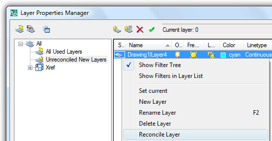
Layer Properties Manager
You can easily rearrange the display order of layer properties by dragging and dropping the column headings and you can control which layer properties are displayed by turning them on or off from a right-click menu. A new Customize Layer Columns dialog box, accessible from the right-click menu, enables you to toggle the visibility of multiple columns. See image.
A new layer creation option in the Layer Properties Manager enables you to create a new layer that is automatically frozen in all viewports. You can access this option from a button as well as from the right-click menu. Additionally, if you right-click on an existing layer, you can freeze that selected layer in all viewports. The Rename option in the right-click menu is also new in AutoCAD 2008. However, you can still rename an existing layer by pressing F2 or by clicking twice (slowly) on the layer name.
You can display objects differently in selected layout viewports while retaining their original layer properties in model space and in other layout viewports. With layer property overrides, you no longer need to use tedious and error-prone methods such as duplicating geometry on separate layers or making copies of xrefs. Instead, when working in a viewport, you can use the Layer Properties Manager to set overrides for VP Color, VP Linetype, VP Lineweight, and VP Plotstyle. When a viewport contains overrides, a Viewport Overrides property filter is automatically created and the override properties are indicated with a different background color. You can select the Viewport Overrides filter to view all layers that contain overrides. A right-click menu in the layer list enables you to remove viewport overrides and a new VPLAYEROVERRIDESMODE system variable enables you to temporarily ignore the overrides for viewing or plotting.
The viewport overrides only affect the display of object properties that are set to BYLAYER. You can quickly change object properties including Color, Linetype, Lineweight, Material, and Plotstyle, of selected objects to BYLAYER using the new SETBYLAYER command. The SETBYLAYER command enables you to modify multiple properties at the same time and it works on objects within blocks and nested blocks as well as the block definitions themselves. A new SetByLayer Settings dialog box, accessible from the SETBYLAYER command, enables you to control which properties to include in the operation.
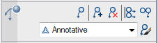
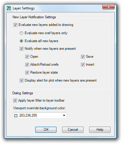
A Settings button in the Layer Properties Manager provides access to the new Layer Settings dialog box where you can enable layer evaluation, apply the layer filter to the layer toolbar, and change the background color for viewport overrides.
The new Layer Panel on the Dashboard acts as a central location for your Layer tools. It includes all of the tools from the Layers toolbar and more!
SetByLayer command forces blocks and other objects to use the color specified by the layer of the block. Supports nested blocks.
Clicking on the Settings button in the Layer Properties Manager shows this dialog box. It allows you to evaluate what should happen when new layers are added to a drawing. Even xrefs can be evaluated and you can be notified on different actions like Open, Save, Attach/Reload xrefs, Insert, Restore layer state and Plot. In a multi-user environment this functionality is useful as a help so you don't end up plotting a drawing with new layers that you are not aware of. But don't rely fully on it since there are some pitfalls as seen further on.
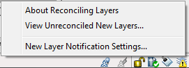
Unreconciled New Layers is a notification that let you know that new layers has been found. If you right click on the Unreconciled New Layers icon you can also access the New Layer Notification Settings.
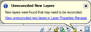
Unreconciled New Layers is a temporary filter that shows the layers that can be reconciled using right click. Being a filter makes it also easy to review the layers before acting on them.
LAYEREVAL and LAYERNOTIFY system variables are saved in each drawing and are the settings for unreconciled layer evaluation and notification. It can be a good idea to enforce the values using acaddoc.lsp. But remember even though you set LAYERNOTIFY to 0 it might still show the notification because the notification is showed before the setting is changed. In a single-user environment or if you don't want to use this new feature just add the following two rows to acaddoc.lsp.
(setvar "LAYEREVAL" 0)
(setvar "LAYERNOTIFY" 0)
Layer notification does NOT happen during publish operations that run in the background (such as publishing from SSM).
The drawing has to be opened and saved in AutoCAD 2008 once for the notification to work properly. The "Resave all sheets" option in SSM does NOT initiate this.
The alert before plot shows for the commands PLOT, -PLOT and PUBLISH. It does NOT show if the command is run from a script file (.SCR) or used in AutoLISP. The alert does NOT show if you start using a plot preview followed by plotting.
Take also a look at you templates and consider if you want layers in them to be unreconciled or reconciled. When saving as a template there is an option for that. Consider also what LAYEREVAL and LAYERNOTIFY should be set to.
Since the baseline that is saved in the drawing needs to know if a layer is reconciled it makes the drawing larger and there is no easy way to purge that information once it has been added. Changing LAYEREVAL and LAYERNOTIFY does not help. But I've made an AutoLISP function that solved this. More about it can be found here. Download for PurgeReconciledLayers.LSP.
An animation is available on this Autodesk blog post by Heidi Hewett.
Introduces the concept of annotation scale as an object property. Designers can set the current scale of a viewport or model space view, and then apply that scale to each object and specify its size, placement, and appearance based on the scale set for the viewport. In other words, annotation scale is now automated. See image.
Now 3DORBIT can be used within the block editor.
Using the parameter description activates tooltips when you hover over dynamic grips.
You can quickly update a block definition in the current drawing to match a block on the tool palette by selecting the new Redefine option from the right-click menu of a block tool.
Using dynamic blocks is more intuitive with new grip tips! When you hover the cursor over a dynamic block grip, the associated parameter description is displayed as a tooltip.
A new option in the XCLIP command enables you to clip the inverse of a selected boundary. For example, if you select the Invert Clip option and then specify a rectangular boundary, everything within the rectangle is removed from the display.
Block attributes have been updated to support multiple lines of text. The Attribute Definition and Edit Attribute dialog boxes include a new Multiple Lines control. When you select Multiple Lines, the Default text box is disabled and you’re provided with access the Multiline Attribute editor.
The Multiline Attribute editor is a simplified version of the MTEXT editor enabling you to enter text, adjust the width for text wrapping, insert fields, underline, and overline. You can use the right-click menu to access additional MTEXT editing options such as Import Text, Background color, and Autocaps. When you define a muiltiline attribute, an additional control in the Attribute Definition dialog box as well as in the Enhanced Attribute Editor, enables you to specify a Boundary Width.
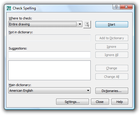
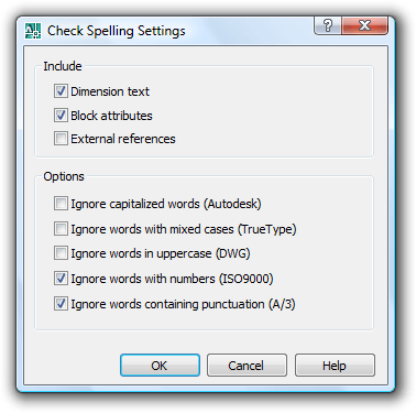
The SPELL command now checks words in dimensions, zooms into words being corrected; added option to ignore words with numbers or words with special characters; where to check selection option.
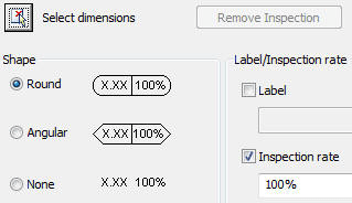
Inspection dimension. This type of dimension has the value, a tag, and a percentage. The command is DIMINSPECT.
![]()
![]()
The DIMJOGLINE command adds or removes a jog line on a linear or aligned dimension. You can edit the jog location using grips and you can turn off the jog or edit its height using the Properties window. Additionally, a new option for linear jog size is included on the Symbols and Arrows tab of the Dimension Style dialog box.
![]()
![]()
The DIMSPACE command adjusts the spacing equally between parallel linear and angular dimensions.
![]()
Here is before and here is the result of the command
The new Dimension Break tool (DIMBREAK command) enables you to break dimension or extension lines where they intersect geometric objects or other dimensions. After specifying the dimension that you want to break, you can select intersecting objects to use as cutting edges or you can choose the Auto or Manual options. When you break a dimension by selecting objects or using the Auto option, the breaks will automatically update when the intersection point moves. If the objects are moved so that they no longer intersect, the break will disappear and if they are moved back the break will automatically return to the proper location. The Manual option enables you to specify start and end point of the break. You can use the Restore option to remove all the breaks from selected dimensions or leaders.
Enhancements to diametric, radial, and jogged radial dimensions enable you to dimension an arc beyond its endpoints. The process for creating these dimensions hasn’t changed. However, when you specify the location of the dimension line, you can drag beyond the endpoints of the arc. AutoCAD will automatically create an arc extension line using the same properties, such as extension line color and extension line offset, as traditional extension lines.
A new option for angular dimensions enables you to place the dimension text outside of the angle being measured. You can access the new option, Quadrant, from the right-click menu when prompted to specify the dimension arc line location. The Quadrant option asks you to specify the quadrant (angle) that you want to dimension separate from specifying the dimension arc line location. If the dimension arc line location that you specify is outside of the quadrant that is being measured, AutoCAD will automatically create an arc extension line to the dimension text.
The Tolerances tab of the Dimension Style dialog box has been updated to include controls for aligning tolerances. You can align stacked tolerances using either the decimal separator or the operation symbol
Properties of objects can be extracted, such as the length of a line or polyline. Custom created rows or columns are retained.
When a DWF file is attached as an underlay you can specify which layers to display. Use the DWFLAYER command.
MicroStation's DGN files can be imported or attached like xrefs. This is limited to 2D drawings only. DGN 8 and XM Files only.
You can use the new DGNATTACH command to attach a DGN file to your AutoCAD drawing as an externally referenced underlay. When you attach a DGN file, it is displayed in the External Reference palette along with other externally referenced files such as images, DWG xrefs, and DWF™ underlays. You can clip the display area of a DGN underlay using the new DGNCLIP command and you can adjust its properties, including contrast, fade, and monochrome, using the Properties palette or through the DGNADJUST command.
You can import V8 DGN data into your AutoCAD session as a new DWG file using the new DGNIMPORT and DGNEXPORT commands. The V8 DGN file format has also been added to the list of supported file types in the IMPORT and EXPORT commands.
After selecting a DGN file to import, AutoCAD displays the Import DGN Settings dialog box. Using this dialog box, you can specify how DGN references should import into the AutoCAD drawing. You can choose to ignore external references, translate reference data into the drawing file, or create a DGN underlay. In addition, you can choose to explode text node to text elements (this option maintains the shape of text created along a path) and you can choose to convert the DGN file to AutoCAD units using the DGN file’s Master or Sub units.
When you export an AutoCAD drawing to DGN file format, AutoCAD displays the Export DGN Settings dialog box. You can choose to translate all DWG references to DGN files, bind all DWG references into one DGN file, or ignore DWG references. You have the option to export externally referenced DGN files (underlays) and you can specify a seed file and units (master or sub). Specifying a seed file allows you to choose to export the data as a 2D or 3D file using imperial or metric units and master or sub units.
Managing Materials
The Materials palette has been updated to provide faster, easier access to materials properties. It includes expandable panels, which enable you to view and edit material setting without having to access multiple dialog boxes.
In the Material Editor panel, you can specify the type of material and select from a wide range of pre-defined templates. The pre-defined templates include appropriate values, such as shininess, opacity, and translucency, for common materials. Using these templates, you can quickly create realistic materials without being a “materials expert.”
The Maps panel enables you apply diffuse, opacity, and bump maps to a material and you can synchronize any or all of the maps with the material. When the maps are synchronized with the material, any changes you make to the material will automatically apply to the specified maps, saving you time and reducing errors. The list of supported map types has been increased to include more procedural maps, such as Checker and Tiles, enabling you to achieve more realistic results than from texture maps alone. A button next to the Map Type provides access to map-specific properties by replacing the current Materials panels with Map-specific panels. When you finish customizing the map properties, you can easily return to the general Materials panels.
The Advanced Lighting Override panel enables you to adjust material lighting parameters for greater realism. Adjustable overrides include Color Bleed, Indirect Bump, Reflectance, and Transmittance.
The Material Offset and Preview panel enables you to preview the material as well as adjust the offset and rotation values.
Applying Photometric Data
In AutoCAD 2008, you can create realistic rendered images by applying real-world photometric properties to light sources. For example, you can reference the lighting catalog for a specific fixture and then use the candela, lumen, or lux values to adjust the lamp intensity. Photometric properties are accessible from the Command line when you create a new light or from the Properties window when you select an existing light.
In addition to the improvements to materials and lighting, a new –RENDER command (don’t forget the dash “-“) enables you to use the command line interface to select from the available render presets. With this command line option, you can automate the rendering process by creating a script to batch render multiple scenes.
RECOVERALL Repairs a damaged drawing and xrefs - The selected drawing file and all attached xrefs, including all nested xrefs, are opened, repaired, resaved, and closed.
- Drawing files are saved in the current drawing file format.
- Copies of the original drawing files are saved as BAK files.
- If the object enabler is present, custom objects are updated.
Results are displayed in the Drawing Recovery Log window. Each drawing file checked includes a Drawing Recovery Log that can be expanded or collapsed. The entire log can be copied to the Windows clipboard with the Copy to Clipboard button.
AutoCAD 2008 includes support for Microsoft® Direct3D® hardware acceleration only in Windows Vista.
New texture compression enhancements will require less video memory and improve performance when display images and textures.
Sheet Set Manager (SSM)
A new option in the right-click menu of the Sheet List tab enables you to publish your sheet set in reverse order. When this option is enabled, the sheets that you plot using Publish to Plotter or Publish using Page Setup Override will plot in reverse of how they are listed in the sheet set manager.
Two additional enhancements provide greater flexibility when plotting from the Sheet Set Manager. When using the Publish using Page Setup Override option to create a DWF file, it will honor the Sheet Set Publish Options enabling you to publish to a multi-sheet DWF file. Also, a new system variable, PUBLISHCOLLATE, allows you to disable homogeneous plotting when you publish using Page Setup Override option. Disabling homogeneous plotting allows plots from other drawings or sheet sets to enter the plot spool.
AutoCAD 2008 includes a new toolbar that enables you to try out some of the functionality available in Autodesk® Impression software. With Impression you can create presentation-ready graphics directly from your AutoCAD drawings.
When you first select a tool from the Autodesk Impression toolbar, you are prompted to download and install the Autodesk Impression technology preview. Once it is installed you can sample some of the Autodesk Impression pen and pencil tools by automatically importing the current AutoCAD view into Autodesk Impression.
After opening a DWG or DWF file in Impression, you can add everything from distinctive line types to textured color fills, using pre-built or custom appearance styles. Libraries of styles can be saved and reused, allowing you to generate unique looks for your work while saving time. Because Impression understands CAD data, you can take advantage of the power of layers and blocks when creating their images.
System requirements
The AutoCAD 2008 DWG file format is the same DWG file format as in AutoCAD 2007.
AutoCAD 2008 can be installed side-by-side with any other AutoCAD or Autodesk vertical solution—including AutoCAD 2008–based products.
Third-party add-on applications based on Visual LISP® or AutoLISP®, VBA, ActiveX® and ObjectARX® programming languages and developer tools for AutoCAD 2007 are compatible with AutoCAD 2008 32-bit. AutoCAD 2008 is binary compatible with 2007 and has the same DWG file format.
Third-party applications for AutoCAD 2004/2005/2006 based on Visual LISP or AutoLISP are also compatible with AutoCAD 2008. Third-party VBA based applications for AutoCAD 2004/2005/2006 are compatible with AutoCAD 2008 32-bit in some cases, but there are instances in which those applications will need to modified. For more details on AutoCAD 2005/2006 VBA-based application compatibility, please refer to www.autodesk.com/developautocad. Third-party applications for AutoCAD 2004/2005/2006 based on ActiveX and ObjectARX will need to be upgraded to be compatible with AutoCAD 2008. Check with your application developer/supplier regarding availability of applications built for AutoCAD 2008.
Third-party applications for AutoCAD 2007 based on ActiveX and ObjectARX will need to be upgraded to work on AutoCAD 2008 64-bit.
|
AutoCAD 2008 supports multiple CPU systems. The performance of AutoCAD graphics and rendering systems will benefit from multiple CPU systems.
ActiveX API
ActiveX API
The following outlines the additions and changes made to the ActiveX API in AutoCAD 2008 and AutoCAD 2008-based products.
Enums
AcEntityName (Changed)
        acMLeader = 48 (New)
AcAttributeMode (Changed)
        acAttributeModeLockPosition = 16 (New)
        acAttributeModeMultipleLine = 32 (New)
AcMergeCellStyleOption (New)
        acMergeCellStyleNone = 0
        acMergeCellStyleCopyDuplicates = 1
        acMergeCellStyleOverwriteDuplicates = 2
        acMergeCellStyleConvertDuplicatesToOverrides = 4
        acMergeCellStyleIgnoreNewStyles = 8
AcUnderlayLayerOverrideType (New)
        acNoOverrides = 0
        acApplied = 1
AcTableFlowDirection (New)
        acTableFlowRight = 1
        acTableFlowDownOrUp = 2
        acTableFlowLeft = 4
AcCellMargin (New)
        acCellMarginTop = 1
        acCellMarginLeft = 2
        acCellMarginBottom = 4
        acCellMarginRight = 8
        acCellMarginHorzSpacing = 16
        acCellMarginVertSpacing = 32
AcCellContentLayout (New)
        acCellContentLayoutFlow = 1
        acCellContentLayoutStackedHorizontal = 2
        acCellContentLayoutStackedVertical = 4
AcCellProperty (New)
        acInvalidCellProperty = 0
        acLock = 1
        acDataType = 2
        acDataFormat = 4
        acRotation = 8
        acScale = 16
        acAlignmentProperty = 32
        acContentColor = 64
        acBackgroundColor = 128
        acTextStyle = 256
        acTextHeight = 512
        acMarginLeft = 1024
        acMarginTop = 2048
        acMarginRight = 4096
        acMarginBottom = 8192
        acEnableBackgroundColor = 16384
        acAutoScale = 32768
        acMergeAll = 0x00010000
        acFlowDirBtoT = 0x00020000
        acContentLayout = 0x00040000
        acDataTypeAndFormat = 6
        acContentProperties = 33662
        acBitProperties = 0x0003c000
        acAllCellProperties = 0x0007ffff
AcGridLineStyle (New)
        acGridLineStyleSingle = 1
        acGridLineStyleDouble = 2
AcDataLinkUpdateDirection (New)
        acUpdateDataFromSource = 1
        acUpdateSourceFromData = 2
AcDataLinkUpdateOption (New)
        acUpdateOptionNone = 0
        acUpdateOptionOverwriteContentModifiedAfterUpdate
               = 0x00020000
        acUpdateOptionOverwriteFormatModifiedAfterUpdate
               = 0x00040000
        acUpdateOptionUpdateFullSourceRange = 0x00080000
        acUpdateOptionIncludeXrefs = 0x00100000
AcCellContentType (New)
        acCellContentTypeUnknown = 0
        acCellContentTypeValue = 1
        acCellContentTypeField = 2
        acCellContentTypeBlock = 4
AcCellState (New)
        acCellStateNone = 0
        acCellStateContentLocked = 1
        acCellStateContentReadOnly = 2
        acCellStateFormatLocked = 4
        acCellStateFormatReadOnly = 8
        acCellStateLinked = 16
        acCellStateContentModified = 32
        acCellStateFormatModified = 64
AcCellOption (New)
        kCellOptionNone = 0
        kInheritCellFormat = 1
AcTextAttachmentType (New)
        acAttachmentTopOfTop = 0
        acAttachmentMiddleOfTop = 1
        acAttachmentBottomOfTop = 2
        acAttachmentBottomOfTopLine = 3
        acAttachmentMiddle = 4
        acAttachmentMiddleOfBottom = 5
        acAttachmentBottomOfBottom = 6
        acAttachmentBottomLine = 7
        acAttachmentAllLine = 8
AcMLeaderType (New)
        acStraightLeader = 1
        acSplineLeader = 2
        acInVisibleLeader = 0
AcMLeaderContentType (New)
        acNoneContent = 0
        acBlockContent = 1
        acMTextContent = 2
AcTextAlignmentType (New)
        acLeftAlignment = 0
        acCenterAlignment = 1
        acRightAlignment = 2
AcTextAngleType (New)
        acInsertAngle = 0
        acHorizontalAngle = 1
        acAlwaysRightReadingAngle = 2
AcBlockConnectionType (New)
        acConnectExtents = 0
        acConnectBase = 1
AcPredefBlockType (New)
        acBlockImperial = 0
        acBlockSlot = 1
        acBlockCircle = 2
        acBlockBox = 3
        acBlockHexagon = 4
        acBlockTriangle = 5
        acBlockUserDefined = 6
AcDrawLeaderOrderType (New)
        acDrawLeaderHeadFirst = 0
        acDrawLeaderTailFirst = 1
AcDrawMLeaderOrderType (New)
        acDrawContentFirst = 0
        acDrawLeaderFirst = 1
AcSegmentAngleType (New)
        acDegreesAny = 0
        acDegrees15 = 1
        acDegrees30 = 2
        acDegrees45 = 3
        acDegrees60 = 4
        acDegrees90 = 6
        acDegreesHorz = 12Classes
IAcadObject (Changed)
        ObjectID - Property (Changed to support 64-bit)
        OwnerID - Property (Changed to support 64-bit)
        ObjectID32 - Property (New)
        OwnerID32 - Property (New)
IAcadDatabase (Changed)
        ObjectIdToObject - Method (Changed to support 64-bit)
        ObjectIdToObject32 - Method (Changed)
IAcadTable (Changed)
        GetBlockTableRecordId - Method (Changed to support 64-bit)
        SetBlockTableRecordId - Method (Changed to support 64-bit)
        GetBlockAttributeValue - Method
              (Changed to support 64-bit)
        SetBlockAttributeValue - Method
              (Changed to support 64-bit)
        GetFieldId - Method (Changed to support 64-bit)
        SetFieldId - Method (Changed to support 64-bit)
        GetBlockTableRecordId32 - Method (New)
        SetBlockTableRecordId32 - Method (New)
        GetBlockAttributeValue32 - Method (New)
        SetBlockAttributeValue32 - Method (New)
        GetFieldId32 - Method (New)
        SetFieldId32 - Method (New)
IAcadPViewport (Changed)
        LabelBlockId - Property (Changed to support 64-bit)
        LabelBlockId32 - Property (New)
IAcadView (Changed)
        LayoutId - Property (Changed to support 64-bit)
        LayoutId32 - Property (New)
IAcadSectionTypeSettings2 (New)
        IntersectionBoundaryVisible - Property (New)
IAcadIdPair (Changed)
        key - Property (Changed to support 64-bit)
        Value - Property (Changed to support 64-bit)
        Key32 - Property (New)
        Value32 - Property (New)
IAcadTableStyle2 (New)
        CreateCellStyle - Method
        CreateCellStyleFromStyle - Method
        RenameCellStyle - Method
        DeleteCellStyle - Method
        GetUniqueCellStyleName - Method
        GetIsCellStyleInUse - Method
        NumCellStyles - Property
        GetCellStyles - Method
        GetTextStyleId - Method
        SetTextStyleId - Method
        GetTextHeight2 - Method
        SetTextHeight2 - Method
        GetAlignment2 - Method
        SetAlignment2 - Method
        GetColor2 - Method
        SetColor2 - Method
        GetBackgroundColor2 - Method
        SetBackgroundColor2 - Method
        GetDataType2 - Method
        SetDataType2 - Method
        GetFormat2 - Method
        SetFormat2 - Method
        GetCellClass - Method
        SetCellClass - Method
        GetRotation - Method
        SetRotation - Method
        GetIsMergeAllEnabled - Method
        EnableMergeAll - Method
        GetGridLineWeight2 - Method
        SetGridLineWeight2 - Method
        GetGridColor2 - Method
        SetGridColor2 - Method
        GetGridVisibility2 - Method
        SetGridVisibility2 - Method
        TemplateId - Property
        SetTemplateId - Method
        GetTextStyleId32 - Method
        SetTextStyleId32 - Method
        TemplateId32 - Property
        SetTemplateId32 - Method
IAcadMLeaderStyle (New)
        Name - Property
        Description - Property
        BitFlags - Property
        ContentType - Property
        DrawMLeaderOrderType - Property
        DrawLeaderOrderType - Property
        MaxLeaderSegmentsPoints - Property
        FirstSegmentAngleConstraint - Property
        SecondSegmentAngleConstraint - Property
        LeaderLineType - Property
        LeaderLineColor - Property
        LeaderLineTypeId - Property
        LeaderLineWeight - Property
        EnableLanding - Property
        LandingGap - Property
        EnableDogleg - Property
        DoglegLength - Property
        ArrowSymbol - Property
        ArrowSize - Property
        TextStyle - Property
        TextLeftAttachmentType - Property
        TextRightAttachmentType - Property
        TextColor - Property
        TextHeight - Property
        EnableFrameText - Property
        AlignSpace - Property
        Block - Property
        BlockColor - Property
        EnableBlockScale - Property
        BlockScale - Property
        EnableBlockRotation - Property
        BlockRotation - Property
        BlockConnectionType - Property
        ScaleFactor - Property
        OverwritePropChanged - Property
        Annotative - Property
        BreakSize - Property
        TextString - Property
        TextAngleType - Property
        TextAlignmentType - Property
IAcadAttribute2 (New)
        MTextAttribute - Property
        MTextAttributeContent - Property
        UpdateMTextAttribute - Method
        MTextBoundaryWidth - Property
        MTextDrawingDirection - Property
IAcadAttributeReference2 (New)
        MTextAttribute - Property
        MTextAttributeContent - Property
        UpdateMTextAttribute - Method
        MTextBoundaryWidth - Property
        MTextDrawingDirection - Property
IAcadMLeader (New)
        ScaleFactor - Property
        LeaderType - Property
        LeaderLineColor - Property
        LeaderLineType - Property
        LeaderLineWeight - Property
        ArrowheadType - Property
        ArrowheadSize - Property
        DogLegged - Property
        DoglegLength - Property
        ContentBlockName - Property
        BlockConnectionType - Property
        TextString - Property
        TextStyleName - Property
        TextJustify - Property
        TextDirection - Property
        TextWidth - Property
        TextHeight - Property
        TextRotation - Property
        TextLineSpacingFactor - Property
        TextLineSpacingDistance - Property
        TextLineSpacingStyle - Property
        TextBackgroundFill - Property
        TextLeftAttachmentType - Property
        TextRightAttachmentType - Property
        LandingGap - Property
        ArrowheadBlock - Property
        ContentBlockType - Property
        LeaderCount - Property
        AddLeader - Method
        RemoveLeader - Method
        AddLeaderLine - Method
        AddLeaderLineEx - Method
        RemoveLeaderLine - Method
        SetLeaderLineVertices - Method
        GetLeaderLineVertices - Method
        ContentType - Property
        GetLeaderIndex - Method
        GetLeaderLineIndexes - Method
        GetVertexCount - Method
        TextFrameDisplay - Property
        StyleName - Property
        GetDoglegDirection - Method
        SetDoglegDirection - Method
        GetBlockAttributeValue - Method
        SetBlockAttributeValue - Method
        GetBlockAttributeValue32 - Method
        SetBlockAttributeValue32 - Method
IAcadPViewport2 (New)
        LayerPropertyOverrides - Property
IAcadTable2 (New)
        IsEmpty - Method
        CreateContent - Method
        MoveContent - Method
        DeleteContent - Method
        GetValue - Method
        SetValue - Method
        SetValueFromText - Method
        GetDataFormat - Method
        SetDataFormat - Method
        GetTextString - Method
        SetTextString - Method
        GetFieldId2 - Method
        SetFieldId2 - Method
        GetBlockTableRecordId2 - Method
        SetBlockTableRecordId2 - Method
        GetBlockAttributeValue2 - Method
        SetBlockAttributeValue2 - Method
        GetCustomData - Method
        SetCustomData - Method
        GetCellStyle - Method
        SetCellStyle - Method
        GetContentColor2 - Method
        SetContentColor2 - Method
        GetDataType2 - Method
        SetDataType2 - Method
        GetTextStyle2 - Method
        SetTextStyle2 - Method
        GetTextHeight2 - Method
        SetTextHeight2 - Method
        GetRotation - Method
        SetRotation - Method
        GetAutoScale2 - Method
        SetAutoScale2 - Method
        GetScale - Method
        SetScale - Method
        RemoveAllOverrides - Method
        GetGridLineWeight2 - Method
        SetGridLineWeight2 - Method
        GetGridLinetype - Method
        SetGridLinetype - Method
        GetGridColor2 - Method
        SetGridColor2 - Method
        GetGridVisibility2 - Method
        SetGridVisibility2 - Method
        GetGridDoubleLineSpacing - Method
        SetGridDoubleLineSpacing - Method
        EnableBreak - Property
        GetBreakHeight - Method
        SetBreakHeight - Method
        GetContentType - Method
        GetMargin - Method
        SetMargin - Method
        GetContentLayout - Method
        SetContentLayout - Method
        GetOverride - Method
        SetOverride - Method
        GetGridLineStyle - Method
        SetGridLineStyle - Method
        InsertRowsAndInherit - Method
        InsertColumnsAndInherit - Method
        GetHasFormula - Method
        GetFormula - Method
        SetFormula - Method
        IsContentEditable - Method
        IsFormatEditable - Method
        GetCellState - Method
        SetCellState - Method
        EnableMergeAll - Method
        IsMergeAllEnabled - Method
        BreaksEnabled - Property
        RepeatTopLabels - Property
        RepeatBottomLabels - Property
        TableBreakFlowDirection - Property
        AllowManualPositions - Property
        AllowManualHeights - Property
        TableBreakHeight - Property
        BreakSpacing - Property
        GetColumnName - Method
        SetColumnName - Method
        SetToolTip - Method
        GetFieldId232 - Method
        SetFieldId232 - Method
        GetBlockTableRecordId232 - Method
        SetBlockTableRecordId232 - Method
        GetBlockAttributeValue232 - Method
        SetBlockAttributeValue232 - Method
        GetGridLinetype32 - Method
        SetGridLinetype32 - Method
IAcadUnderlay2 (New)
        UnderlayLayerOverrideApplied - Property
IAcadBlock2 (New)
        AddMLeader - Method
IAcadModelSpace2 (New)
        AddMLeader - Method
IAcadPaperSpace2 (New)
        AddMLeader - Method
IAcadDocument (Changed)
        HWND - Property (Changed to support 64-bit)
        HWND32 - Property (New)
IAcadApplication (Changed)
        HWND - Property (Changed to support 64-bit)
        HWND32 - Property (New)
Still missing
Still missing. Wish list for the next time.
Support for multileader styles using the RENAME, FILTER, -PURGE commands and the Design Center.
FIND dialog box should be modeless to be able to easy zoom and pan transparently during the command.
FIND should be able to find and maybe even replace text that is nested in blocks or xrefs.
FIND command should also highlight the text that is found.
When showing the layout tabs it would be good to lock the position of the Model tab if there are multiple layout tabs that eventually hides the model tab.
Hide/Unhide layout tabs like in Excel 2007.
Since spell check zoom into the text it can affect performance on large drawings that needs to regen a long time it might be good to have some legacy functionality left to speed up the process.
There should be an option to exclude some linetypes from being scaled when using annotation scaling. Typical ones are BATTING and ZIGZAG.
Bcount command should support dynamic blocks.
The annotative option in the Hatch and Gradient dialog box and the Block Definition dialog box should persist.
It should be possible to specify a hatch to be annotative on a palette tool.
In dialog boxes like the Open dialog box it should be possible to save changes like column width, sorting, grouping etc.
Snap hierarchy for object snap. For example automatically find first mid then end then int.
Connections for objects like in Actrix or Visio.
Dynamic 3D blocks.
Enhance the Enhanced Attribute Editor so that the value could be added directly within the list grid box.
Ability to edit attributes in place without the Enhanced Attribute Editor. As an option.
Enhance text editing. When you edit one text click on another text and edit that one directly. This will save keystrokes compared to today when you have to exit out the editor and then double click on the second text object to edit.
Add an option to start an empty drawing when the last drawing is closed. The reason is that functionality like SSM doesn't work without a drawing open.
Import/export tools that support native SketchUp files (SKP).
Support creation of animations to DWF.
3D DWF should support hyperlinks.
Save current layer filter to the drawing so it can be restored automatically when reopened. Include also a drawing system variable.
Reorder the location of anchored palettes and be able to lock the order.
Specify the height of anchored palettes individually. Now all are maximized in height.
When changing a Cylinder solid to Elliptical it should be possible to set Elliptical to No.
When changing a Cylinder solid to Elliptical it should be possible to directly change major and minor radius with the grips.
Polygon Mesh creation as real surfaces.
Live section that work on a per viewport basis.
FlatShot support for named blocks.
SSM should maintain focus from placing one view to the next. Each time you go back to the resource drawing tab after placing a view the focus reverts back to the top of the list.
SSM: Support of completely blank fields or empty fields (especially when using SSM). Not with "----". It could be that they where visible on the screen but not plotable Should be an option if you still want "----". Workaround: entering ALT-0160 (Non-break Space) on the keyboard followed by an enter. To do it hold down the ALT key and type the numbers 0 1 6 0 on the numeric keypad. This requires a True Type Font to work.
Right click on a toolbar and end up at the right place to edit it in CUI.
CUI: Support for tool palettes and tool palette groups.
CUI: be able to disable/enable items. Have them show up only in CUI.
Eattext should be able to retain the settings of a customized table.
Eattext should be able to include the file name and the path of the extracted drawing.
Support of the new OpenType fonts. Suffix=OTF and also TTF. OpenType fonts that use PostScript outlines.
In the layer properties manager multiple xrefs can be selected but only one show it's layers. All selected xrefs should show their layers or you should not be able to select multiple xrefs.
When zooming with the mouse wheel in perspective it would help if the zooming was centered on the crosshair just like when in parallel projection mode.
Make the Minstert command more user friendly with dialog box UI.
Existing bugs
Existing bugs, defects, feature limitation or other issues.
FIND - the "zoom to" button in the find command dialog box does not zoom correctly if the ucs is non world or the text found is not on a world ucs. (Solved in AutoCAD 2009)
The Search tab in Visual LISP help is not working. (Solved in AutoCAD 2009)
SSM: Renaming the layout on a drawing breaks the hyperlinks in the Sheet List Table to the Sheet in question.
When moving a clipped xref the objects outside the clipping shows up. This didn't happen in AutoCAD 2005.
Adding \X before <> on an arc dimensions make the arc sign double in size and the measurement disappears.
2004 introduced a bug (or change) when it comes to dimensions. The placement of alternate units are now above the dimension line. In 2002 it was below. "\X" doesn't help as primary unit suffix. But "\X " works as a workaround, observe the space after the X, change also the placement of the alternate units to be After the primary value.
Selecting multiple files in the opening dialog box and pressing enter doesn't work.
The Rename dialog box doesn't accept renaming of for example blocks with names including the # character.
Dimensioning with DIMSCALE set to 0 and using VPMAX doesn't work as expected. The scale of the viewport is not respected.
In some extreme situations where the coordinates are large zoom to object does not really zoom up the object as one would expect.
Sometimes when you show the AutoCAD Text Window there is no way to scroll. Workaround is to resize the window.
I define this as a bug since it's so annoying. If you have removed some of the default annotation scales in a drawing and inserts a drawing that has not been saved with AutoCAD 2008 and does not contain any annotation scales all default annotation scales are added anyway. It seems like it is hardcoded in the program so a hotfix from Autodesk is needed. (Solved in AutoCAD 2009)
Using PURGE command deletes standard multileader style. You cannot use the MLEADER command after you have used the PURGE command with the Purge Nested Items check box selected, as this purges the standard multileader style. Workaround here. (Solved in AutoCAD 2009)
Using FIND and find and replace on MTEXT with paragraph spacing removes the paragraph spacing formatting and leaves a ; character. (Solved in AutoCAD 2009)
.NET API: The property Ole2Frame.IsLinked and Ole2Frame.LinkPath fails on a LINKED OLE object. (Solved in AutoCAD 2009)
DWG to PDF plotting has problems to accurately center a sheet on the paper. It's getting better with a higher DPI but not much. (Solved in AutoCAD 2009)
In VBA this will fail: ThisDrawing.Application.Preferences.User.HyperlinkDisplayTooltip = False with Run-time error '-2147467259 (80004005)': Method 'HyperlinkDisplayTooltip' of object 'IAcadPreferencesUser' failed
getfiled bug hangs AutoCAD (probably related to Windows Vista) See this post.
Using an ampersand (&) in naming layouts has changed. A layout named so&so shows up like soso. Notice that the character after & is underlined. Probably a bug that slipped through. (Fixed in SP1)
Custom scales which exist in the nested xrefs are no longer duplicated in the host drawing. (Fixed in SP1)
All dynamic block properties are now not correctly extracted. (Fixed in SP1)
There are some problems with rotated multi-line attributes (Mattributes) definitions. They automatically move a the distance of the text height. The move happens when the drawing/block is saved and opened. (Fixed in SP1)
Unresolved fields in multi-line attribute makes the definition move. The move happens when the drawing/block is saved and opened. (Fixed in SP1)
Linetypes not always display properly after zooming operations. (Fixed in SP1)
Use this link to report a bug to Autodesk that bugs you: http://www.autodesk.com/submitbug
Removed
Removed
The option to enable the Startup dialog has been removed from the Options dialog box. The Startup dialog can be enabled by changing the value of the STARTUP system variable. Set the value to 1 to enable and 0 to disable.
Tips & Tricks
Tips & Tricks
REGEN has no function in 3D so if you really need to regen use the undocumented REGEN3 command.
Screen flashing can be a problem related to some Microsoft Intellipoint drivers. Try another driver version.
Readme
Readme
Installation and Configuration
Installing from Dual CD/DVD ROM Drive Systems
- Installation fails if you attempt to install AutoCAD with both installation CDs in each drive of a dual CD/DVD ROM drive system. When asked for the second installation disk, the disk in the second CD drive is not recognized. You must replace the first disk with the second disk in the same drive in order to complete the installation.
HTML Help Fails When Launched from a Network Drive
- In some cases, help files cannot be opened from a network location. This is due to a known Microsoft issue. For more information, visit http://support.microsoft.com/kb/892675.
Disk Imaging
- If your computer is in a SATA RAID environment and you are experiencing licensing instability, using disk imaging software to distribute Autodesk products can cause problems with product activation. If you attempt to activate the product in a SATA RAID environment, you may get an "Activation code limit exceeded" message.
Error Reporting
- The Error Report message, which is displayed when your AutoCAD session ends unexpectedly, encourages you to send error reports to Autodesk. Error reports help Autodesk identify and resolve many problems with the product. The Error Report message is similar to the one that is shown when an application ends unexpectedly on a computer running Microsoft® Windows® XP. Error reporting records the portion of the product that is in use when the work session ends. In the Error Report message, click Optional Data, enter the following information, and then click Send Report:
- Information about what you were doing in AutoCAD before your session ended unexpectedly
- Your contact information
Providing this information helps Autodesk reproduce the error and fix it as quickly as possible. If an AutoCAD session ends unexpectedly but the Error Report message is not displayed, make sure that the REPORTERROR system variable is set to 1
Some Non-English 2006 Product Line Installers Fail if 2008 Products Are Already Installed
- The installer for the Autodesk 2008 product line installs .NET Framework 2.0. This prohibits the installation of some non-English Autodesk 2006 products after a 2008 product has been installed. Reinstall .NET 1.1 and its related service pack to install 2006-based products.
- Insert the 2006-based product CD in the drive.
- Browse to \Bin\acadFeui\support\dotnetfx\ and double-click dotnetfx.exe to install .NET 1.1.
- From the same folder, double-click NDP1.1sp1-KB867460-X86.exe to install .NET 1.1 Service Pack1.
- To install a non-English version, do the following:
- Browse to \Bin\acadFeui\support\dotnetfx\language\ and install langpack.exe.
- Install the 2006-based products.
Licensing
Updated PLIST Information Is Ignored
- Updated Product List (PLIST) information is ignored in a distributed license server environment. Periodically, Autodesk might update the PLIST information in a network license file.
For instance, you have an existing license file containing PLIST information residing on the first server of a distributed license server environment. If you purchase another Autodesk product with a license file containing updated PLIST information, and it resides on a different server in the distributed server environment, the older PLIST data from the first server is recognized instead of the newer PLIST data.
To make sure the updated PLIST file is read obtain a new license file from Autodesk that contains the latest PLIST information. Alternatively, you could add the updated PLIST to the first server in the distributed license server environment to make sure that it is always read.
Network License Guide Update
- Due to late changes in the AutoCAD 2008 Installation Wizard, the Network Licensing Guide procedures for installing the Network License Manager and Network License Activation Utility are confusing. The following procedures are updated for clarity.
Install the Autodesk Network License Manager
To install the Autodesk Network License Manager
- In the AutoCAD 2008 Installation wizard, click Install Tools and Utilities.
- On the Welcome to the AutoCAD 2008 Installation wizard page, click Next.
- On the Select the Products to Install page, make sure Network License Manager is selected and click Next.
- Review the Autodesk software license agreement for your country or region. You must accept this agreement to proceed with the installation. Choose your country or region, click I Accept, and then click Next.
Note If you do not agree to the terms of the license and wish to terminate the installation, click Cancel.
- On the Review - Configure - Install page, click Configure.
- Click the Network License Manager tab, if multiple product were selected in step 3.
- On the Select the Installation Location page, either accept the default installation path (C:\Program Files\Autodesk Network License Manager\) or click [...] to specify a different path. If you enter a path that does not exist, a new folder is created using the name and location you provide. Click Configuration Complete.
Warning Do not install the Network License Manager on a remote drive. When you install the Network License Manager files, you must provide a path to a local drive. You must specify the drive letter; the universal naming convention (UNC) is not supported.
- Once returned to the Review - Configure - Install page, click Install to begin installing the Network License Manager and any other selected tools and utilities.
- When the Installation Complete page displays, click Finish.
Install the Network License Activation Utility
To install the Network License Activation utility
- In the AutoCAD 2008 Installation wizard, click Install Tools and Utilities.
- On the Welcome to the AutoCAD 2008 Installation wizard page, click Next.
- On the Select the Products to Install page, make sure Network License Activation Utility is selected and click Next.
- Review the Autodesk software license agreement for your country or region. You must accept this agreement to proceed with the installation. Choose your country or region, click I Accept, and then click Next.
Note If you do not agree to the terms of the license and wish to terminate the installation, click Cancel.
- On the Review - Configure - Install page, click Configure.
- Click the Network License Activation Utility tab, if multiple product were selected in step 3.
- On the Select the Installation Location page, either accept the default installation path (C:\Program Files\Autodesk Network License Manager\Network License Activation Utility\enu\) or click [...] to specify a different path. If you enter a path that does not exist, a new folder is created using the name and location you provide. Click Configuration Complete.
- Once returned to the Review - Configure - Install page, click Install to begin installing the Network License Activation Utility and any other selected tools and utilities.
- When the Installation Complete page displays, click Finish.
Hardware
SATA RAID Environment Failure
- After you activate and then restart your product, you receive error 0.1.0011 or 11.1.6011 and are required to reactivate. This problem can occur for Autodesk's 2006-, 2007-, and 2008-based products on computers with SATA RAID controllers.
See Autodesk Activation Update for a Product Support solution to this problem.
Graphics Card Driver Update
- For the best program performance, verify and update your graphics card driver. For more information, see Graphics Card Driver Update.
Remote Access Applications
- It is not recommended that you use any type of remote access application in conjunction with AutoCAD when AutoCAD is configured to use hardware acceleration. Most remote access applications cannot support hardware acceleration, and as a result, can cause general display failure and instability. If you need to use remote access applications, disable hardware acceleration or use the /NOHARDWARE command line switch to start AutoCAD in Software mode.
Hewlett-Packard Designjet Printer Driver
- Autodesk no longer ships the Windows system printer driver for the Hewlett-Packard Designjet series on the product CD. If you need this driver, you can download it at http://www.designjet.hp.com.
Hardware Certification Database
- Please visit our Hardware Certification website at http://www.autodesk.com/autocad-graphicscardupdate to download and install the latest hardware certification XML file.
Graphics Card Driver Update
It is recommended that you verify and update your graphics card driver to optimize AutoCAD. Use the following procedure to identify your current graphics card driver.
To identify your graphics card driver
- Start AutoCAD.
- At the command line, enter 3dconfig.
- In the Adaptive Degradation and Performance Tuning dialog box, click View Tune Log.
- Review the 3D Device section for information about your system's graphics card driver and driver version.
If you find that you do need to update your driver, visit http://www.autodesk.com/autocad-graphicscard to look for a certified driver for your graphics card. If you do not find one, visit the graphics card manufacturer's website.
Note: If the graphics card manufacturer does not have an updated driver, check the system manufacturer's website. Companies like IBM, Hewlett Packard, and Dell often supply their own system drivers.
Drawing Environment
DWF Underlays
- It is recommended that you insert DWF underlay files on locked layers to avoid editing them by mistake. When zooming in on DWF underlay files and then using a window selection method, the DWF underlay may be selected even though the geometry in the underlay does not appear to be selected.
- It is recommended that you do not use DWFATTACH and PASTECLIP for DWF underlays while using REFEDIT.
- When using REFEDIT in a drawing, if you use PASTECLIP to paste a DWF underlay, you may be unable to save back your changes. The following message may be displayed:
This error message may also be displayed when you have a DWF underlay attached in the host drawing and then try to use DWFATTACH on the same DWF underlay file in the xref during REFEDIT. The workaround to save back your other REFEDIT changes is to delete the DWF underlay that you attached or pasted during the REFEDIT session.
Cannot save back changes because objects in the working set reference objects outside of the working set. The Refedit session is still active. Press F2 after dismissing the dialog to see the list of missing references.Tool Palettes
- Tool palettes created in the current release should not be used in previous releases.
Opening Sample Drawing Files in Windows Vista
- Due to Windows Vista restrictions, all sample files found in the AutoCAD Sample folder and subfolders are read-only. Sheet Set Manager sample files can be opened in the Sheet Set Manager but cannot be changed.
Searching Files in Windows Vista
- To search contents within drawing files in Windows Explorer for Windows Vista, use the Advanced Search and select the "Include non-indexed, hidden and system files" option.
Autodesk i-drop
- For i-drop to operate properly on a system running Windows Vista, the user should be set to Run as Administrator.
3D Environment
AutoCAD 2007 exposed a new 3D Modeling environment which you can access by means of the VISUALSTYLES command and choosing any non-2D style. The 3D environment has some behavioral differences when compared to the legacy 2D drafting environment, such as:
- Draw order is not supported in 3D
- Memory usage in 3D is higher
- REGEN and REGENALL does not necessarily clean up display artifacts. To reset the display, cycle VISUALSTYLES between 2D and non-2D styles.
Direct 3D with Windows Vista
- When Direct 3D is enabled in a Windows Vista environment, the cursor appears as black and white instead of color in non-2D visual styles. Any changes to the cursor from the Options dialog box are not enabled in this environment.
Materials
Procedural Materials Are Not Converted by CONVERTOLDMATERIALS
- Procedural materials that are applied to objects in AutoCAD 2007 models are not converted by the CONVERTOLDMATERIALS command in AutoCAD 2008.
Animation and Rendering
Animation Output
- The Quicktime Player cannot play MOV files saved with characters that are not native to the current operating system.
- Windows Vista versions K and N (available in Korea and Europe) do not come with Windows Media Player installed. In order to use the animation feature in AutoCAD, download the latest version of Media Player from the Microsoft website.
Featured Content and Technologies
- To install featured visualization content and technologies, enable the Communication Center and configure it to receive updates. Once it is configured, a new channel called "Featured Content and Technologies" will be visible and content will be available for download.
Other Drafting Issues
Annotative Attributes in Multileader Content Blocks
- It is not recommended to use annotative attributes in multileader content blocks. Doing so may cause visibility issues with those blocks. Use only non-annotative attributes and non-annotative blocks as content in annotative multileader objects.
Solid Hatches
- Drawings that contain solid hatches may produce larger plot files than drawings with other types of hatches.
Visibility of Hatches
- The HPMAXLINES system variable was introduced to prevent systems from running out of memory. Based on the current HPMAXLINES setting, some hatches may not display. To fix this problem, change the HPMAXLINES value.
Annotative Hatches in Viewports
- In model space viewports (TILEMODE = 0), annotation scales added to hatches via the Properties palette may not appear as specified in other viewports. To prevent this problem, do one of the following:
- Use the shortcut menu instead of the Properties palette to add annotation scales.
- Switch to model space (TILEMODE = 1) to add annotation scales.
If you have already encountered this problem, close and reopen the drawing to properly display the hatch scale in the viewport or viewports.
Nonrectangular Viewports
- Assigning a noncontinuous linetype to a nonrectangular viewport can result in model space geometry that is irregularly clipped inside the viewport, or it can cause AutoCAD to become unstable.
- When you use the JPGOUT, PNGOUT, BMPOUT, and TIFOUT commands in a layout that contains nonrectangular viewports with a 3D visual style and with all objects and viewports selected, portions of other viewports may be obscured and objects may not be visible. You can use the PUBLISH command to create more accurate raster output.
- Do not freeze layers that contain nonrectangular viewports; instead, turn off layers with nonrectangular viewports or set the Plot property of the layer to No Plot. When you freeze a layer that contains a nonrectangular viewport, the viewport boundary becomes rectangular. Objects in the viewport that should be clipped by the boundary of the nonrectangular viewport appear to be clipped, but when you regenerate or plot the drawing, the objects are not clipped as you expect. To correct the problem once it exists, you must thaw the layer and then regenerate the drawing.
External References
- Due to the xref polling cycle, you can encounter a time lag when attempting to use the Manage Xrefs icon to reload DWG xrefs. Referenced DWG files are not ready to be reloaded by this method until you see the balloon notification on the Manage Xrefs icon. To expedite the reloading process, use one of the following methods:
- Right-click the reference drawing in the File References list of the External References palette and then click Reload.
- Click Reload All References on the button controls at the top of the External References palette.
- Enter -XREF at the Command prompt and use the Reload option.
Saving Drawings to Previous File Formats
- When moving or copying surface objects from the current release to R14, a fatal error may occur.
Project Organization
Sheet Sets
- The Sheet Set Manager is not fully functional if
- A command is active.
- No drawing is open.
- The sheet set is locked by another user.
- A lock icon displayed in front of the sheet set name in the Sheet Set Manager indicates that the sheet set is locked. Hold your cursor over the lock icon to view a tooltip that shows who has the sheet set locked.
- When you select a sheet in the Sheet Set Manager, the sheet's status may be listed incorrectly as Locked for Edit by Unknown in the Details area. To update the sheet's status, open the sheet.
- If you remove a sheet from a sheet set and then import the sheet back into the sheet set, fields that display sheet set information in block attributes are displayed as pound signs. To correct these fields, you can either recreate the field or reinsert the block. If you recreate the field, because the sheet is already in a sheet set, you should use a sheet set property field, not a placeholder field.
- Sheet set fields (fields that were selected from the sheet set category) behave differently than other types of fields. By default, other types of fields update automatically when you save the drawing or when you use REGEN. In contrast, sheet set fields store the last values that were used, and they display these stored values if the information referenced by the sheet set field is not accessible. To update the value in a sheet set field, use the UPDATEFIELD command. If the information referenced by the sheet set field is still not accessible, the value for the field will be displayed as ####.
Using One DWT for Page Setups and Blocks on a Network
- Some sheet set functions are unavailable when two network users access a sheet set that uses the same drawing template file (DWT) for label and callout blocks, sheet template, and page setup overrides. To avoid this problem, do not use the same DWT file for storing page setups and block libraries.
Plot and Print Drawings
Plot Large Raster Images
- Two new system variables were added in AutoCAD 2007 to allow you greater control over plotting drawings that contain large raster image attachments or when plotting high resolution, large, rendered/shaded viewports on large size media.
- RASTERTHRESHOLD
- Type: Integer
- Saved In: Registry
- Initial Value: 20
- Specifies a raster threshold in megabytes. If the plotted raster image exceeds this threshold, the availability of system memory is checked. The plot is aborted if the image is too big for the available memory.
- RASTERPERCENT
- Type: Integer
- Saved In: Registry
- Initial Value: 20
- Sets the maximum percentage of available virtual memory that is allowed for plotting a raster image.
Publish Drawings
DWF Files
- Raster images in DWF underlays are not plotted when plotting to DWF.
- Plotting DWF underlay files that contain raster images can produce unexpected results.
Text
MTEXT Heights
- The MText height value will be reset to 0 if its default height wasn't modified during creation.
Language
Multiple-Language Support
- Drawing properties in AutoCAD 2008 are saved with Unicode characters. For instance, if you save the latest format drawing containing multiple language drawing properties to a 2004-format drawing, the drawing properties are converted to the native characters of the current Windows language. If text cannot be converted to the native characters, it is saved to CIF codes (\U+nnnn) or MIF codes (\M+nxxxx).
- When saving the latest format drawing to a 2004-format drawing, any new symbol or dictionary names (for example, layout name, text style name, dimension style name) created in AutoCAD 2008 are saved in the language that was used when the symbol names were created.
- When you copy and paste characters that have been created using a language other than the system language, the characters may not be displayed correctly. You can correct this display with the In-Place Text Editor.
To correct the display to show the original language
- Double-click the text to open it in the In-Place Text Editor.
- Right-click inside the editor. Click Character Set and choose the original language.
- In order to view and edit drawings with characters that are not included in the languages specified for your operating system, make sure supplemental language support is installed in your computer operating system. You can specify the language in the Regional and Language Options dialog box, available from the Windows Control Panel. (You may be able to view text that uses SHX fonts without specifying extra language support.)
- Text styles for Asian languages that use SHX and Big Font can support characters only from the same code page. For example, text styles that use a Japanese Big Font cannot support German or Korean characters. (English characters, which are part of every code page, are supported.) Multiple-language support for non-Asian languages is supported for text styles that use SHX fonts with Big Fonts disabled. (The SHX font must define the required characters.)
- To make it easier to use multiple-language multiline text on operating systems that support different languages, use a TrueType font setting in the In-Place Text Editor.
- Multiple-language support does not exist in some earlier versions of AutoCAD. For example, when you save a file to AutoCAD 2000 format, the contents of multiple-language multiline text may be corrupted. This problem is more likely to happen when you open and save a drawing on an operating system with a system language setting that differs from the system in which the drawing was last saved.
Folder or File Names
- AutoCAD 2006, AutoCAD LT 2006, and prior versions were not Unicode applications. When sharing drawings with earlier, non-Unicode, versions, use ASCII characters to ensure compatibility when you save files, insert xrefs, and specify folder paths.
Double-Byte Character Issues
Data Source Names
- Character codes (such as 0x??41 and 0x??61) that are used for data source names may not be handled correctly. This problem occurs when you create multiple data sources using optional names (Japanese) specified in the database configuration. As a result, some of the data source names may not be listed. When this problem occurs, you can change the name of the unlisted data source to another name.
Subobject and Object Cycling
- Subobject and object cycling using CTRL + SPACEBAR and SHIFT + SPACEBAR does not work in Chinese (PRC and Taiwan) versions of Microsoft Windows. When using the Chinese IME, these key combinations do the following:
- CTRL + SPACEBAR toggles Chinese IME.
- SHIFT + SPACEBAR toggles double-byte and single-byte English characters.
Inside the IME, you can change the accelerator key combinations. You can change the default actions of CTRL + SPACEBAR and SHIFT + SPACEBAR to something that does not conflict with the AutoCAD CTRL + SPACEBAR and SHIFT + SPACEBAR behavior.
Text Display
Vertical Text for Asian Languages
- SHX fonts - Text can be created with SHX fonts and Big Fonts for vertical display in the same way as for previous releases. For best results, use the single-line TEXT command, not MTEXT. You can select a vertical style in the Text Style dialog box.
TrueType fonts - You still select fonts starting with the @ sign, but now the text is automatically rotated 270 degrees. (In AutoCAD 2005 and earlier versions, you had to manually rotate this text.) Vertical cursor movement is now supported for vertical text.Font Display
- If the default font doesn't support the characters you enter using the In-Place Text Editor (MTEXT command), an alternative font is usually substituted.
- CIF or MIF codes entered with the In-Place Text Editor (MTEXT command) or with the DTEXT command are now automatically converted to display the actual characters.
Updated bigfont.ini
- AutoCAD 2007 and AutoCAD 2008 are handling custom SHX Big Fonts differently than AutoCAD 2006 and earlier versions. If custom SHX Big Fonts are used in your drawing files, you need to add the SHX Big Font names and their code page ID into the bigfont.ini file in your Support folder. Please refer to the header section of this bigfont.ini file to learn how to add them.
Command Entry
AltGR and Key Combinations
- ALTGR+ any key results in a halt of command entry. This is caused by the CTRL+ALT combination of implied faces extrusion. If you use an ALTGR keyboard layout, the workaround is to set IMPLIEDFACE to 0 (zero).
Developer Information
Changes That May Affect Scripts
Changes to the following commands or system variables may affect pre-existing scripts:
- EXTEND - For the EXTEND command, if you do not select an object at the Select Objects to Extend prompt, you are now prompted to specify the opposite corner of a crossing window. This change may affect pre-existing scripts that call EXTEND and supply a pick point that selects no objects. You can fix legacy scripts by omitting points that do not select objects.
- -INSERT - If you use the Scale Uniformly option in the Block Definition dialog box, you are no longer prompted to enter separate scale factors for X,Y,Z coordinates when you insert a block using the -INSERT command.
- MENULOAD - By default, the MENULOAD command loads only CUI files in AutoCAD 2006 or later releases. To load an MNU or MNS file in AutoCAD 2006 or later release, you must explicitly include the extension in the file name, as shown in the following example:
(command "menuload" "myMenu.mnu")
However, rather than changing your code, it is strongly recommended that you open your legacy menu files in AutoCAD 2008 before running applications that use them. AutoCAD automatically converts them to CUI files, and the CUI files are loaded by existing code that uses the file name without an extension.
Legacy code that specifies an MNU, MNS, or MNC extension should be changed to reference a CUI file, and AutoCAD 2007-based applications should ship with CUI files, not MNU, MNS, or MNC files.- TRIM - For the TRIM command, if you do not select an object at the Select Objects to Trim prompt, you are now prompted to specify the opposite corner of a crossing window. This change may affect pre-existing scripts that call TRIM and supply a pick point that selects no objects. You can fix legacy scripts by omitting points that do not select objects.
Visual LISP
Notifications
- In some cases, the vlr-sysVarWillChange and vlr-sysVarChanged notifications are triggered multiple times for one system variable change.
Grips
- AutoCAD no longer supports grips on unselected objects. As a result, the gripset argument of the AutoLISP sssetfirst function is ignored, and the ssgetfirst function returns nil for the first selection set returned.
True Color
- If you have a full installation of AutoCAD, utilities for working with True Color are located in the \Sample\VisualLISP folder, in the color-util.lsp file. The utilities can be used for operations related to True Color, such as getting the components of a true color number, converting a color index or color name to a true color value, returning a DXF group code list, and working with an entity list.
The following AutoLISP functions provide access to the True Color user interface:
(acad_truecolordlg color [allowbylayer] [currentlayercolor]).
Prompts for colors through a dialog box. The color parameter is a dotted pair describing the default color; the first element of the dotted pair must be one of the color-related DXF group codes (62, 420, or 430). If the allowbylayer parameter is present and is not nil, the ByLayer and ByBlock buttons are shown. When the operation is successful, the function returns a list of one or more dotted pairs describing the color selected. The last dotted pair in the list indicates the color selected. The function returns nil if the user cancels the dialog box.
(acad_truecolorcli color [allowbylayer] [alternatePrompt]).
Prompts for colors at the command line. The first two parameters are identical to acad_truecolordlg, and the third parameter is an optional prompt string. If this string is omitted, the default value is "New color."The entmod and entmake Functions
- In AutoCAD 2004 and later releases, the entmod and entmake functions have new behavior in color operations. DXF group code 62 holds AutoCAD Color Index (ACI) values, but code 420 holds true color values. If the true color value and ACI value conflict, AutoCAD uses the 420 value, so the code 420 value should be removed before attempting to use the code 62 value. For more information, perform a full installation of AutoCAD and see the color-util.lsp file located in the \Sample\VisualLISP folder.
Load Errors
- If LOAD encounters an error while loading a separate-namespace VLX, some functions may have been exported to the current document namespace before the error was detected. You must be sure to fix the error, rebuild, and reload the VLX in order to ensure that the correct version of all functions is exported to the current document.
- When the CUILOAD command loads a partial menu in MDI, the MNL file for that menu loads once for every open document, with all user interaction occurring in the current document. To avoid redundant printed messages or user prompts when AutoCAD is initiated with multiple drawings, it is recommended that you do not include any user interaction in MNL LISP code. Instead, use MNL code to load any needed AutoLISP files for subsequent menu item selections. Use the acad.lsp or acaddoc.lsp files to execute AutoLISP code to be processed when a drawing is opened.
Display of the Multiple Design Environment Dialog Box
- The Multiple Design Environment dialog box allows you to change the default functionality of the initialization of the AutoLISP environment. This dialog box is displayed under the following conditions:
If all these conditions are true, the Multiple Design Environment dialog box is displayed the first time that a second document is opened in each session.
- The Do Not Show value of the AcadLspAsDocDlg registry key is set to 0.
- There are no scripts running, and there is no AutoLISP or ActiveX application running.
- The ACADLSPASDOC system variable is set to 0.
- An acad.lsp file exists in the AutoCAD search path.
- An acaddoc.lsp file does not exist in the AutoCAD search path.
- The SDI system variable is set to 0.
ActiveX and VBA
Visibility of the AutoCAD Process
- VBA scripts that run at startup should check whether the AutoCAD process is visible or invisible. If the process is invisible, the script should not execute, because the process may be performing background plotting or publishing operations. To check whether the AutoCAD process is visible or invisible, you can use the Visible property of the Application object in the AutoCAD Object Model.
Updates & Service Packs
Updates & Service Packs
- Plot to PDF Not Centered With Custom Margins Hotfix
- Hotfix - Vault ACAD Addin (cumulative)
- Non-Unicode Multiline Text Hotfix
- Hotfix - Autodesk Activation Update
- Live Update Hotfix
- Open Failure from Windows Explorer Hotfix
- WAN Acceleration 2008 Hotfix
- Raster issues after installing Service Pack 1
- Hotfix - Linetype display
- Hotfix - Redundant License Server
- Hotfix – Secondary User Windows Start menu launch error
- AutoCAD 2008 Service Pack 1 for AutoCAD Revit Architecture Suite 2008
- AutoCAD 2008 Service Pack 1
- AutoCAD 2008 Service Pack 1 for AutoCAD Revit Structure Suite 2008
- Hotfix - DWF Package Not Viewable in Autodesk Design Review 2008
- Hotfix – AutoCAD Online PDF’s Update (Czech only)
- Hotfix - Hungarian Layout Switching
- Hotfix - Vista Group Policy Objects
- Hotfix - Inventor DWG Files Opened in AutoCAD 2008 may not Display Annotations
- Hotfix - Live Update
- Hotfix - Autodesk® idrop 64-bit
- Hotfix – AutoCAD Users Guide Online PDF Update (German only)
- Hotfix - Unable to Use or ADD DWG Files to ADMS 2008
- AutoCAD®/AutoCAD®LT 2008 Online Help File Update - Japanese only
New Commands
New Commands:
ANNORESET - Resets the location of all scale representations for an annotative object to that of the current scale representation
ANNOUPDATE - Updates existing annotative objects to match the current properties of their styles
ATTIPEDIT - Changes the textual content of an attribute within a block
AUTOPUBLISH - Publishes drawings to DWF files automatically
CUSTOMERINVOLVEMENTPROGRAM - Opens the Customer Involvement Program (CIP) dialog box.
DGNADJUST - Changes the display options of selected DGN underlays
DGNATTACH - Attaches a DGN underlay to the current drawing
DGNCLIP - Defines a clipping boundary for a selected DGN underlay
DGNEXPORT - Creates one or more V8 DGN files from the current drawing
DGNIMPORT - Imports the data from a V8 DGN file into a new DWG file
DIMBREAK - Adds or removes a dimension break
DIMINSPECT - Creates or removes inspection dimensions
-DIMINSPECT - Creates or removes inspection dimensions
DIMJOGLINE - Adds or removes a jag line to a linear or aligned dimension
DIMSPACE - Adjusts the spacing equally between parallel linear and angular dimensions
DWFLAYERS - Controls the display of layers in a DWF underlay
FREEPOINT - Creates a target point light without a prompt for the target point
FREESPOT - Creates a free spotlight, which is similar to a spotlight without a specified target
FREEWEB - Creates a free weblight which is similar to a weblight without a specified target
LAYERSTATE - Saves, restores, and manages named layer states also directly from DWG, DWT, or DWS files.
MLEADER - Creates a line that connects annotation to a feature
MLEADERALIGN - Organizes selected multileaders along a specified line
MLEADERCOLLECT - Organizes selected multileaders containing blocks as content into a group attached to a single leader line
MLEADEREDIT - Adds leader lines to, or removes leader lines from, a multileader object
MLEADERSTYLE - Defines a new multileader style
NEWVIEW - Expedites the creation of a new view
OBJECTSCALE - Adds or deletes supported scales for annotative objects
QUICKCUI - Displays the Customize User Interface dialog box in a collapsed state
RECOVERALL - Repairs a damaged drawing and xrefs
-RENDER - Command prompt version of the RENDER command
RENDEREXPOSURE - Provides settings to interactively adjust the lighting global for the most recent rendered output
TARGETPOINT - Creates a target point light
TPNAVIGATE - Displays a specified tool palette or palette group
WEBLIGHT - Creates a weblight
Changed Commands
Changed Commands:
3DCONFIG - Added plot emulation and texture compression options
-3DCONFIG - Added plot emulation and texture compression options (Command prompt version)
ATTDEF - Added support for annotative scaling
-ATTDEF - Added support for annotative scaling (Command prompt version)
ATTEDIT - Multiple-line attribute support
BATTMAN - Added support for annotative scaling
BLOCK - Added support for annotative scaling
-BLOCK - Added support for annotative scaling (Command prompt version)
CHPROP - Added support for annotative scaling
CUI - Added dashboard panel customization and some enhancements for customizing toolbars
DASHBOARD - Added access to the Customize User Interface from the shortcut menu
DIMANGULAR - Added the Quadrant option
DIMDIAMETER - Added the Extension line option
DIMJOGGED - Added the Extension line option
DIMRADIUS - Added the Extension line option
DIMSTYLE - Added new tolerance alignment option, size option for linear jog, and break spacing
-DIMSTYLE - Command prompt version of DIMSTYLE (Command prompt version)
DISTANTLIGHT - Modified to support entering photometric properties
EATTEXT - Now activates the DATAEXTRACTION command rather than the Attribute Extraction wizard
-EATTEXT - Command prompt version of the EATTEXT command (Command prompt version)
ETRANSMIT - Added support for visual fidelity
HATCH - Added support for annotative scaling
-HATCH - Added support for annotative scaling (Command prompt version) HATCHEDIT Added support for annotative scaling
-HATCHEDIT - Added support for annotative scaling (Command prompt version)
INSERT - Added support for annotative scaling
-INSERT - Added support for annotative scaling (Command prompt version)
-LAYER - Added option to import layer states from drawings, the Edit option now includes Material and Description suboptions, the Import option now includes DWG/DWS/DWT formats, and the Export option includes the LAY file format (Command prompt version)
MATCHCELL - Added support for double line borders, border linetypes, and new cell formats
MTEXT - Added support for annotative scaling
-MTEXT - Added support for annotative scaling (Command prompt version) MVIEW When used on a layout, a new option, Layer, removes all layer property override values and resets them back to their corresponding global properties
MVIEW - When used on a layout, a new option, Layer, removes all layer property override values and resets them back to their corresponding global properties
OPTIONS - Added the Maintain Visual Fidelity check box to the Open and Save tab as well as the Display Drawing Status Bar check box to the Display tab
PASTESPEC - Enhanced for pasting Microsoft Excel data from the clipboard to create a data link to this information immediately
PLOT - Affected by the hardware configuration settings Plot Emulation and Texture Compression
POINTLIGHT - Start and end limits for attenuation are supported with the Direct 3D driver; also added prompting for area-sampled shadow options and photometric prompting
QSELECT - Added support for annotative scaling
SPELL - Now checks words in dimensions, zooms into words being corrected; added option to ignore words with numbers or words with special characters
SPOTLIGHT - Start and end limits for attenuation are supported with the Direct 3D driver; also added prompting for area-sampled shadow options and photometric prompting
STYLE - Added support for annotative scaling
-STYLE - Added support for annotative scaling (Command prompt version)
TABLE - Added From Style and Data Link branches
-TABLE - Added From Style and Data Link branches (Command prompt version)
TABLESTYLE - Defines a new table style
TEXT - Added support for annotative scaling
VIEW - Modified to support the new sky background option, when applicable
-VPORTS - Added option, Layer, removes all layer property override values and resets them back to their corresponding global properties (Command prompt version)
XCLIP - Added the Invert option
Removed or Obsolete Commands
Removed or Obsolete Commands:
ASSIST - Opens Quick Help in the Info palette, which provides context-sensitive information
ASSISTCLOSE - Closes Quick Help and the Info palette
New System Variables
New System Variables:
3DCONVERSIONMODE - Used to convert material and light definitions
3DSELECTIONMODE - Controls the selection precedence of visually overlapping objects when using 3D visual styles
ANNOALLVISIBLE - Hides or displays annotative objects that do not support the current annotation scale
ANNOAUTOSCALE - Updates annotative objects to support the annotation scale when the annotation scale is changed
ANNOTATIVEDWG - Specifies whether or not the drawing will behave as an annotative block when inserted into another drawing
ATTIPE - Controls the display of the in-place editor used to create multiline attributes
ATTMULTI - Controls whether multiline attributes can be created
AUTODWFPUBLISH - Controls whether the AutoPublish feature is on or off
CANNOSCALE - Sets the name of the current annotation scale for the current space
CANNOSCALEVALUE - Returns the value of the current annotation scale
CMLEADERSTYLE - Determines the current multileader style
COPYMODE - Controls whether the COPY command repeats automatically
DATALINKNOTIFY - Controls the notification for updated or missing data links
DGNFRAME - Determines whether DGN underlay frames are visible or plotted in the current drawing
DGNOSNAP - Controls object snapping for geometry in DGN underlays
DIMANNO - Indicates whether or not the current dimension style is annotative
DXEVAL - Controls when data extraction tables are compared against the data source, and if the data is not current, displays an update notification
HPMAXLINES - Controls the maximum number of hatch lines that will generate
LAYEREVAL - Controls when the Unreconciled New Layer filter list in the Layer Properties Manager is evaluated for new layers
LAYERNOTIFY - Specifies when an alert displays for new layers that have not yet been reconciled
LAYLOCKFADECTL - Controls the dimming for objects on locked layers
LIGHTINGUNITS - Controls whether generic or photometric lights are used, and indicates the current lighting units
LIGHTSINBLOCKS - Controls whether lights contained in blocks are used when rendering
LINEARBRIGHTNESS - Controls the global brightness level of the drawing when using default lighting or generic lights
LINEARCONTRAST - Controls the global contrast level of the drawing when using default lighting or generic lights
LOGEXPBRIGHTNESS - Controls the global brightness level of the drawing when using photometric lighting
LOGEXPCONTRAST - Controls the global contrast level of the drawing when using photometric lighting
LOGEXPDAYLIGHT - Controls if exterior daylight is used when using photometric lighting
LOGEXPMIDTONES - Controls the global mid tones level of the drawing when using photometric lighting
MSLTSCALE - Scales linetypes displayed on the model tab by the annotation scale
PERSPECTIVECLIP - Determines the location of eyepoint clipping
PUBLISHCOLLATE - Controls whether plotting a sheet set, multi-sheet plot file, or plot spool file can be interrupted by other plot jobs
RENDERUSERLIGHTS - Controls whether user lights are translated during rendering
SAVEFIDELITY - Controls whether the drawing is saved with visual fidelity
SELECTIONANNODISPLAY - Controls whether alternate scale representations are temporarily displayed in a dimmed state when an annotative object is selected
SETBYLAYERMODE - Controls which properties are selected for SETBYLAYER
TABLETOOLBAR - Controls the display of the Table toolbar
TEXTOUTPUTFILEFORMAT - Provides Unicode text file output options
VPLAYEROVERRIDES - Indicates if there are any layers with viewport (VP) property overrides for the current layout viewport
VPLAYEROVERRIDESMODE - Controls whether layer property overrides associated with layout viewports are displayed and plotted
VSFACEHIGHLIGHT - Controls whether layer property overrides associated with layout viewports are displayed and plotted
Existing
Changed System Variables:
AFLAGS - Added a value for the new Multiple Lines mode
DCTMAIN - Displays the three letter keyword of the current main spelling dictionary
DIMSCALE - Automatically set to 0 when an annotative dimension style is made current
Removed or Obsolete System Variables
Removed or Obsolete System Variables:
ASSISTSTATE - Indicates whether the Info palette that displays Quick Help is active or not