
Retired by Autodesk in 2010
Previous AutoCAD version AutoCAD 2006 and newer version AutoCAD 2008.
New and/or enhanced functions
New and/or enhanced functions and some bug fixes.
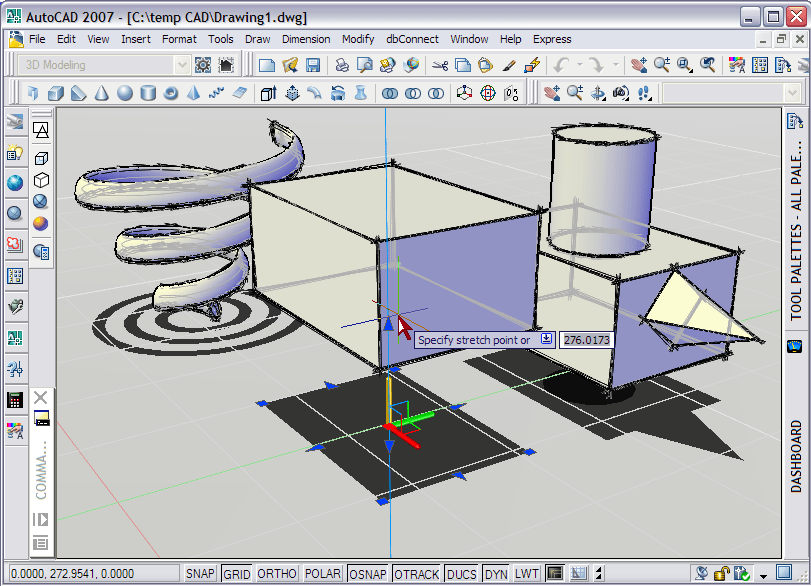
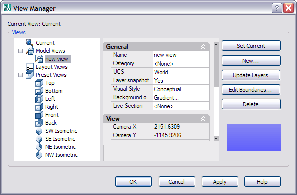
The above picture of AutoCAD 2007 shows a lot of the news.
It is a 3D model on screen with shadows, conceptual visual style, edge overhand, edge jitter, silhouette edges, obscured edges in a perspective projection that you can work in.
Anchored palettes as icons only to the left and with text and icons to the right.
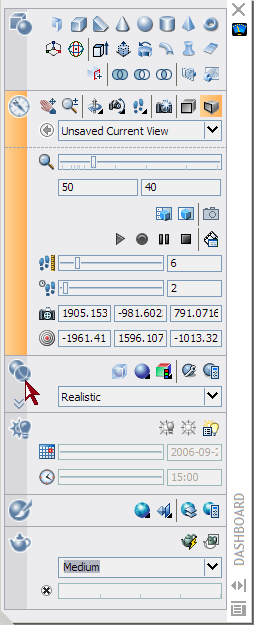
The dashboard palette is a single palette with most 3D features. The command is DASHBOARD. You cannot remove or add commands to it but you can make some settings like selecting what control panels to show and link the control panel icon to a tool palette group so that when you clock on the icon a specific group is activated. Right click on the icon to set the tool palette group to be activated when clicking on the icon.
Save screen space and have layout and model tabs on your status bar if you want to.
 New DWG file format.
 ![]() Now it's AutoCAD 2007 DWG. And there is a new
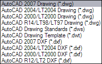
Now it's AutoCAD 2007 DWG. And there is a new ![]() icon for the DWGs in Explorer. So users without AutoCAD 2007 needs to download DWG TrueConvert™ that can batch convert from AutoCAD 2007 DWG to 2004, 2000 and R14. Or you can use SaveAs that allows to save down to R14 DWG and R12 DXF as well as several versions in between.
icon for the DWGs in Explorer. So users without AutoCAD 2007 needs to download DWG TrueConvert™ that can batch convert from AutoCAD 2007 DWG to 2004, 2000 and R14. Or you can use SaveAs that allows to save down to R14 DWG and R12 DXF as well as several versions in between. 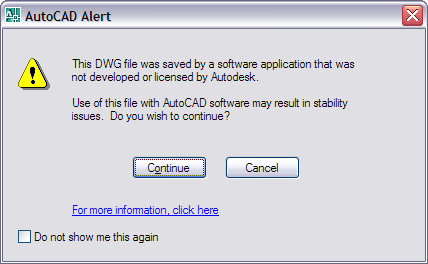 AutoCAD 2007 will optionally warn users when the DWG file they are opening was saved using an application that was not created by an Autodesk product or RealDWG licensee. What is a Trusted DWG? Answer here. In the tray within AutoCAD you will either see
 ![]() for a Trusted Autodesk DWG and
for a Trusted Autodesk DWG and ![]() for a Non Autodesk DWG.
for a Non Autodesk DWG.
3D news and enhancements
3D news and enhancements
3D solid primitive creation and modification is made easier. Grips or the Properties palette can be used to change the shape of the object.
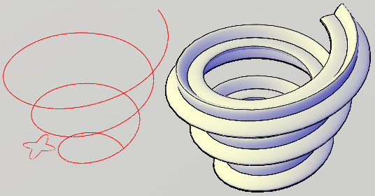
Helix is a new kind of object that can be created. When exploded it converts to a spline object.
Pyramid is a new command that as expected creates a 3D pyramid.
The new POLYSOLID command (as well as a new object) enables you to specify the length, width, and justification of a rectangular profile and then draw the path, similar to drawing a Polyline. Access familiar Polyline options including Arc, Undo, and Close and the geometry dynamically displays and changes as you draw. They can be created from an existing line, 2D polyline, arc, or circle.
Extrude a an open geometry like a line or arc and you get an extruded surface. The new object is Extrudedsurface.
When prompted to select the objects to extrude, press the CTRL key and select a face to use the face of an existing solid or surface to create a new solid.
The REVOLVE command has been updated to produce either surfaces or solids based on the profile and axis of rotation.
A face of an existing solid or surface can be used to create a new solid using the REVOLVE command. When prompted to select the objects to revolve, press the CTR key and select a face.
The new SWEEP command provides considerable flexibility for sweeping profiles along a path. It can automatically align a profile with a path and with a variety of options including scale factor, twist angle, and banking. Depending if the profile is an open or closed curve, the SWEEP command will create a surface or solid.
The new LOFT command interpolates a surface or solid through a set of cross section curves. If the cross section curves are open, a surface is created and if they are closed, a solid is created.
The new PLANESURF command enables you to create an accurate planar surface. Pick a rectangular area or use the Object option to select one or more objects that form an enclosed area.
The SLICE command has been updated to enable selection of a surface as the slicing object.
The new THICKEN command adds thickness to a surface, turning it into a solid.
The new CONVTOSOLID command enables to convert a 2D object with thickness into an equivalent extruded solid.
The new CONVTOSURFACE command enables you to converts a variety of objects into surfaces.
The EXPLODE command will explode solids into regions and surfaces. Planar faces of solids are converted into regions, and curved faces of solids are converted into surfaces.
The new XEDGES command enables you to extract wireframe geometry from solids, surfaces and regions.
The new command IMPRINT imprints an edge on a 3D solid.
The INTERFERE command has been updated to make it easier for you to identify when solids interfere with each other. It also includes the ability to select blocks and external references when searching for interferences and to select individual nested solids within a block or xref.
The new 3DALIGN command makes it easy to align objects in 3D.
Face, Edge, Vertex Manipulation
Transparent Solids
New Dynamic UCS functionality automatically switches your current workplane reducing the need for you to manually change your UCS. The Dynamic UCS is enabled by default and you can toggle it on or off with the DUCS option on the status bar. With DUCS enabled, you can pass your cursor over the edge of a face; the face will highlight indicating that it is being used to establish a temporary UCS.
AutoTracking and Object snaps have been enhanced to detect and track in the Z direction. Even in Perspective mode.
3DOrbit can be run transparently with commands active (press the Shift key and middle mouse button). The new default, Constrained Orbit mode, prevents you from inadvertently rolling the geometry completely over. If you want the ability to spin the view without constraints, you can use the Free Orbit mode (press the Shift+Ctrl key and middle mouse button).
The new 3DSWIVEL command enables you to maintain your position while spinning your viewpoint; similar to spinning a camera on a tripod.
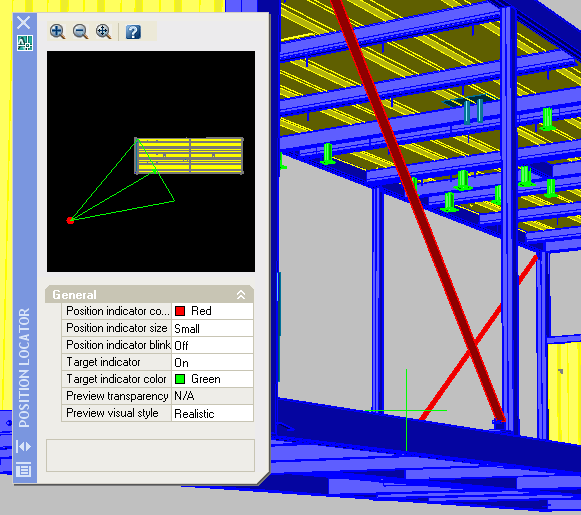
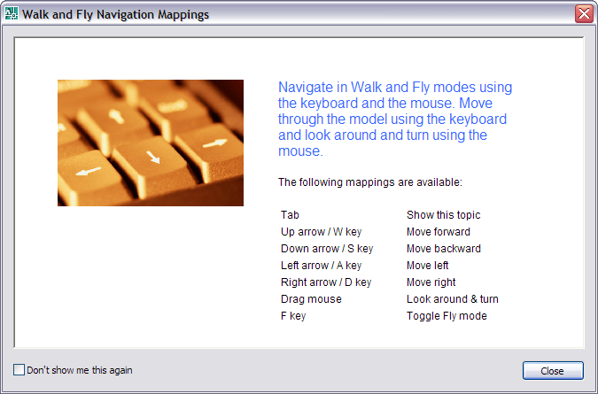 The new 3DWALK command enables you to walk through your design using the arrow keys as well as the W,A,S, and D keys. A position locator displays the camera and target positions enabling you to graphically edit them by dragging the indicator icons. Using the expanded navigation controls in the dashboard, you can adjust the step size and speed as well as the camera and target locations. Recording tools enable you to record the screen as you walk through your design and save the animation to AVI, MPG, or WMV format for future playback.
The CAMERA command has been improved so it's easier to create and manipulate the view.
Toggle between Parallel and Perspective projections by selecting the appropriate buttons on the Dashboard or by setting the new PERSPECTIVE system variable.
Lighting is easier to work with.
Real-Time Shadows.
Many new materials are provided that you can apply to your objects for presentation purposes. Easier to apply to objects or individual faces. Drag-and-drop.
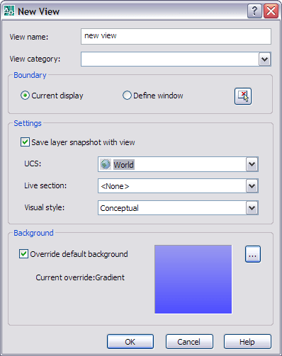
Visual Styles enable you to quickly change the appearance of your model. They replace the previous shademode functionality and provide even greater control and flexibility. You can apply a variety of properties to affect the opacity, background, shadows, edges, faces and more.
Gooch is used for the conceptual Visual Style and uses cool and warm colors instead of dark and light to enhance the display of faces that might be shadowed and difficult to see in a realistic display. The effect is less realistic, but it can make the details of the model easier to see.
SECTIONPLANE, LIVESECTION, JOGSECTION and FLATSHOT are used to add section planes, make it live, add jogs and create a 2D flat snapshot of a 3D model.
3D DWF publishing has been integrated into the AutoCAD User Interface.
Mental Ray renderer. That means high quality like in Viz/Max.
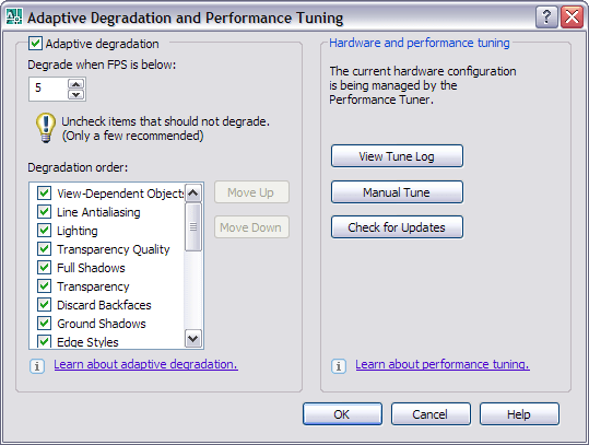
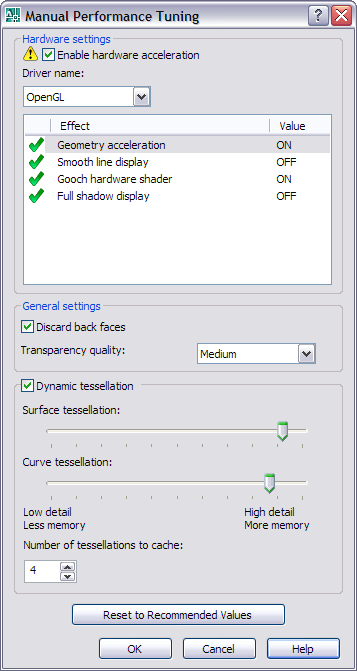
If you want to use all the 3D and visual features in AutoCAD 2007 www.autodesk.com\autocad-graphicscard helps when looking for hardware. A better graphic card can do a lot.
2D news and enhancements
2D news and enhancements
DWF files can be attached as underlays, clipped, adjusted (fade, contrast, monochrome) and snapped to. (But you cannot bind it or explode it. Layers are not supported. The line weight or width cannot be changed.)
Print to PDF (2D only). It's a basic functionality available from the Plot dialog box as DWG To PDF.pc3. SHX and TTF fonts are saved as graphics though and affects the file size (files are bigger) and ability to search text (not possible) within the PDF.
Layer Express Tools (now in the Format menu) and the Chspace command (in the Format menu) are now part of core AutoCAD.
MTEXTFIXED set to 2 and MTEXTED set to “Internal:”. Text that would otherwise be difficult to read (if it is very small, very large, or is rotated) is displayed at a legible size and is oriented horizontally so that you can easily read and edit it. DTEXT or TEXT commands also works better than in AutoCAD 2006. After adding the first text just click somewhere else and add a new text. Use Shift+TAB and edit the previous text and TAB to edit the next text.
The Mtext editor has been updated to support the Shift+Tab key combination as a method for removing one level of nesting from a numbered or bulleted list.
Object fields allow selection of objects either in paperspace or modelspace. LISP variables are also supported in fields.
The table formula function accept a comma as a period.
Dynamic block lookup tables now by default are set to "Allow Reverse Lookup". - "Allow Reverse Lookup enables the lookup property for a block reference to be set from a drop-down list that is displayed when the lookup grip is clicked in a drawing. Selecting an option from this list changes the block reference to match the corresponding input property values in the table."
It's possible to change dynamic block properties during Insert.
When using the DIST command in paper space, the model space distance will be returned as long as OSNAPing to geometry within the same viewport.
External References Palette 
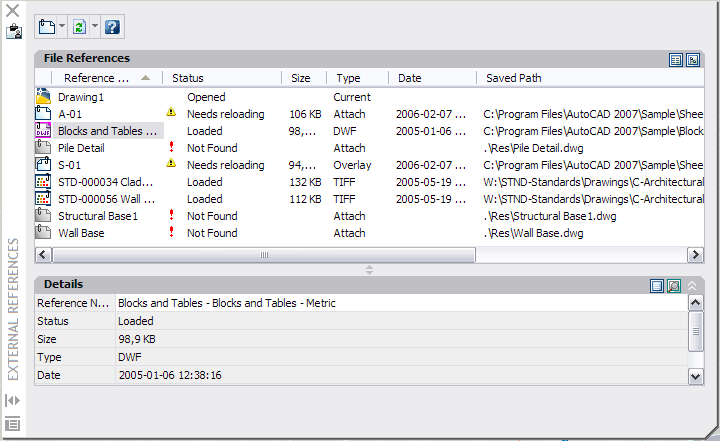 You might see it referred to Xref ESW where ESW stands for Enhanced Secondary Window. You can have it open all the time and dock or anchor it. It handles DWG, Images and DWF. Later Microstation DGN file format will be added. Image extensions *.cals and *.pict are added as accepted.
Other
Other
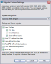 Migrate your settings is updated.

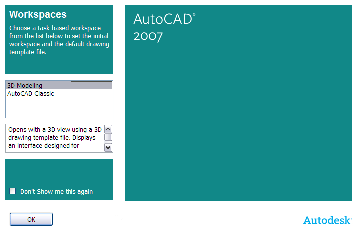 Select workspace to start with.
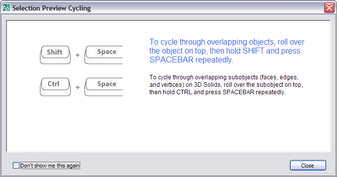 "To cycle through overlapping objects, roll over the object on top, then hold SHIFT and press SPACEBAR repeatedly. To cycle through overlapping subobjects (faces, edges, and vertices) on 3D Solids, roll over the subobject on top, then hold CTRL and press SPACEBAR repeatedly."
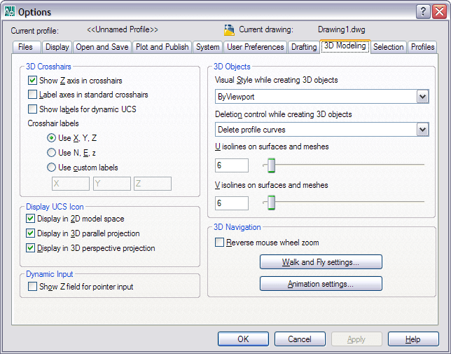 A new 3D Modeling tab has been added to the Options dialog box. Customize the appearance of the 3D crosshairs. Specify when to display the UCS ICON. Enable the Z-field for pointer input. Apply visual styles. Specify object deletion behavior for profiles and other defining geometry. Specify the number of U and V lines on surfaces and meshes. Reverse the behavior of the mouse wheel zoom. Specify the navigation settings for walk-throughs and animations.
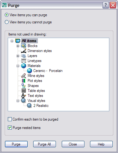
The purge (and -purge) command now also purges materials and visual styles not used in the drawing.
 Customize what happens when double-clicking using CUI. There is a new Double Click Actions node.
CUI functionality has been updated enabling you to drag and drop from the command list onto tool palettes.
CUI performance has been improved.
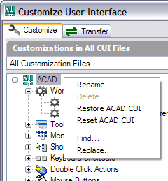
If you have messed up with the CUI file it can be restored or reset. If restore is selected the backup acad.bak.cui is used. If reset is selected the file is taken from C:\Program Files\AutoCAD 2007\UserDataCache\Support
Starting AutoCAD with the command line switch /w designates which workspace in the loaded CUI files should be restored on startup.
The Sheet Set Manager has been updated to enable you to select multiple sheets and then drag them to a new location or subset within the sheet list.
When you insert a block, the Properties Palette displays block properties enabling you to edit some values, such as color and layer, upon insertion.
When you enter an unacceptable value in a tooltip for dynamic input, the value automatically highlights enabling you to reenter the value.
AutoCAD functionality automatically removes old drawing recovery files.
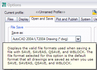 To make it easier for those needing to work with older file formats of DWG you have been able to automatically save to older versions. Now the Wblock command also respects this setting. It's also possible to manually specify the file type in Wblock (Write Block) using the browse for file name and path dialog box.
When reference editing a drawing it keeps the version of the xreffed drawing. You will get this dialog box message if you Refedit (reference edit) something other than a 2007 DWG: "The Xref selected references a previous drawing file format. Edits saved back to the Xref file will be in the release format of the referenced drawing file."
Resaving all sheets in Sheet Set Manager (SSM) retains the version of the drawing.
The Sheet Set data DST file has the same format (1.1) as previous version. That means that you can work in a sheet set in AutoCAD 2007 and also work in AutoCAD 2006 with it. Especially if you have set the options to save to 2004 DWG file format. Even though it's not needed other than the 2007 DWG format drawings will not be possible to open in 2006.
Subscription customers will get free access to Vault. Doesn't work with Sheet Set Manager though.
MicroStation V8's DGN format (2D geometry and annotations only) might be added before the release of AutoCAD 2008.
Help
Help
 Many Flash animations that are useful. Open help and click the Show Me Animations link in the right pane under the General Information section.
A lot of images that are helpful.
The New Features Workshop has been updated with the latest news in AutoCAD 2007.
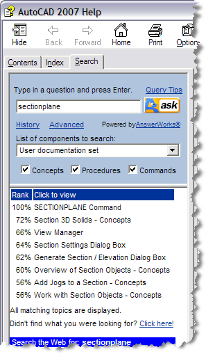
The tab Ask Me in the Help has been renamed to Search and there are added a History and Advanced link. The functionality in the old Search tab has been removed.
In VisualLISP help the favorites tab is removed.
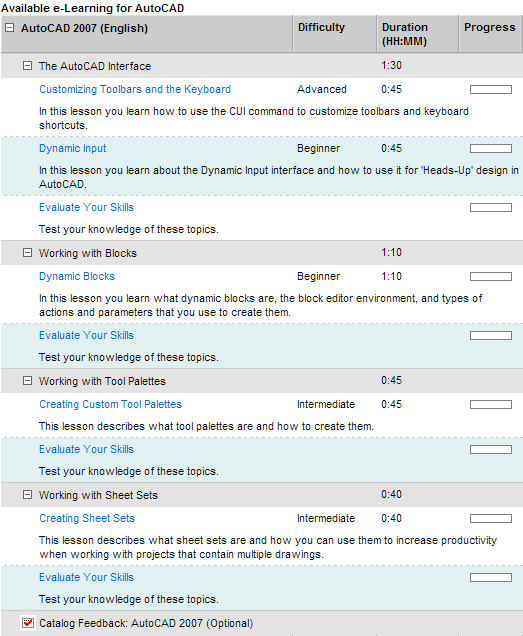
e-Learning for subscription customers.
AutoCAD 2007 is breaking binary compatibility with previous releases of AutoCAD. This means that ObjectARX Applications built to run with versions of AutoCAD prior to 2007 will not load. Check if your 3:rd party application is or will be compatible with AutoCAD 2007.
ObjectARX 2007 and .NET applications requires to be compiled using Microsoft® Visual Studio® 2005.
Visual C# or Visual Basic Express editions are not suggested for AutoCAD .NET development. These versions do not support debugging your project while it is loaded in AutoCAD. Other than that it works if you want to start playing with managed .NET code.
Unicode Support in ObjectARX APIs - “Unicode provides a unique number for every character, no matter what the platform, no matter what the program, no matter what the language” – www.unicode.org.
Managed .NET API
Managed .NET API News and Enhancements:
3D Solids and Surfaces - Create and manipulate solids and Autodesk Shape Manager (ASM) surfaces. Revolution, sweep, and lofting, section and flatten programmatically.
Rendering and Materials - Settings for both Generic and the mental ray® renderer, fog and depth cue. Render to specific targets like Window, Viewport or an Image File. Per-entity materials, translucence and luminance etc.
Lights - Various light types such as Point, Spot, and Distant lights. Default lighting, brightness, contrast, and ambient light properties, sunlight and shade studies, casting and receiving shadows.
Visual Styles - ‘Visual Styles’ are replacing the AutoCAD Shademode functionality.
Sub-Entity Selection and Manipulation - New input-context reactors, extended ‘Selection Set’ APIs with several new global acedSSSubentXXX() functions and context menu support for specific sub-entities. Additional new AcDbEntity overrides for sub entity support in custom entities.
CUI and Workspace API - You can automate the updates to the main CUI, create a custom CUI, and create custom workspaces from scratch.
Managed Tool Palette API - Managed Wrapper for AcadToolImpl class.
Lisp-callable functions in .NET - Pass data to / from Auto LISP® application. Define functions which can be accessed from AutoLISP.
Bug fixes
Bug fixes
There is a problem with the precision with the new calculator (CAL). Try for example 611-602.555 that should result in 8.445 and notice that the result is not what you expect. It returns 8.4450000000001. (Solved in AutoCAD 2007)
A minor visual defect is that if you is highlighting an object with rollover and then press CTRL+A the other objects gets dashed but not that object. (Solved in AutoCAD 2007)
When having multiple viewports in modelspace or paperspace and editing text using mtedit other views can be changed automatically. The ruler can also show up in other viewports. (Solved in AutoCAD 2007)
Migration Mayhem 2 (2006 to 2006 SP1, affects earlier releases) Cadalyst Bug Watch (Solved in AutoCAD 2007)
Misplaced Menu Memory (2006 to 2006 SP1) Cadalyst Bug Watch (Solved in AutoCAD 2007)
There are several bug fixes. More to come here...
System requirements
Besides minimum system requirements there are also additional recommendations for 3D use.
Minimum: 512 MB RAM
Recommended for 3D: Windows XP Pro SP 2, 2 GB RAM, 3.0 GHz or greater processor, 128 MB or greater, OpenGL-capable workstation-class graphics card
Autodesk will release an update for AutoCAD 2007 and AutoCAD LT 2007 in the coming months that will add support for Windows Vista 32-bit versions.
ActiveX API
ActiveX API
The following outlines the additions and changes made to the ActiveX API in AutoCAD 2007 and AutoCAD 2007-based products.
Enums
AcEntityName (Changed)
        acDwfUnderlay = 46 (New)
        acDgnUnderlay = 47 (New)
AcViewportScale (Changed)
        acVp1_1 = 2 (New)
        acVp1_2 = 3 (New)
        acVp1_4 = 4 (New)
        acVp1_8 = 5 (New)
        acVp1_10 = 6 (New)
        acVp1_16 = 7 (New)
        acVp1_20 = 8 (New)
        acVp1_30 = 9 (New)
        acVp1_40 = 10 (New)
        acVp1_50 = 11 (New)
        acVp1_100 = 12 (New)
        acVp2_1 = 13 (New)
        acVp4_1 = 14 (New)
        acVp8_1 = 15 (New)
        acVp10_1 = 16 (New)
        acVp100_1 = 17 (New)
        acVp1_128in_1ft = 18 (New)
        acVp1_64in_1ft = 19 (New)
        acVp1_32in_1ft = 20 (New)
        acVp1_16in_1ft = 21 (New)
        acVp3_32in_1ft = 22 (New)
        acVp1_8in_1ft = 23 (New)
        acVp3_16in_1ft = 24 (New)
        acVp1_4in_1ft = 25 (New)
        acVp3_8in_1ft = 26 (New)
        acVp1_2in_1ft = 27 (New)
        acVp3_4in_1ft = 28 (New)
        acVp1in_1ft = 29 (New)
        acVp1and1_2in_1ft = 30 (New)
        acVp3in_1ft = 31 (New)
        acVp6in_1ft = 32 (New)
        acVp1ft_1ft = 33 (New)
AcSaveAsType (Changed)
        ac2007_dwg = 36 (New)
        ac2007_dxf = 37 (New)
        ac2007_Template = 38 (New)
        acNative = 36 (Changed)
AcValueDataType (New)
        acUnknownDataType = 0
        acLong = 1
        acDouble = 2
        acString = 4
        acDate = 8
        acPoint2d = 16
        acPoint3d = 32
        acObjectId = 64
        acBuffer = 128
        acResbuf = 256
        acGeneral = 512
AcValueUnitType (New)
        acUnitless = 0
        acUnitDistance = 1
        acUnitAngle = 2
        acUnitArea = 4
        acUnitVolume = 8
AcParseOption (New)
        acParseOptionNone = 0
        acSetDefaultFormat = 1
        acPreserveMtextFormat = 2
AcFormatOption (New)
        kFormatOptionNone = 0
        acForEditing = 1
        acForExpression = 2
        acUseMaximumPrecision = 4
        acIgnoreMtextFormat = 8
AcTableStyleOverrides (Changed)
        acTitleRowDataType = 24 (New)
        acHeaderRowDataType = 25 (New)
        acDataRowDataType = 26 (New)
        acCellDataType = 148 (New)
AcSectionState (New)
        acSectionStatePlane = 1
        acSectionStateBoundary = 2
        acSectionStateVolume = 4
AcSectionSubItem (New)
        acSectionSubItemkNone = 0
        acSectionSubItemSectionLine = 1
        acSectionSubItemSectionLineTop = 2
        acSectionSubItemSectionLineBottom = 4
        acSectionSubItemBackLine = 8
        acSectionSubItemBackLineTop = 16
        acSectionSubItemBackLineBottom = 32
        acSectionSubItemVerticalLineTop = 64
        acSectionSubItemVerticalLineBottom = 128
AcSectionType (New)
        acSectionTypeLiveSection = 1
        acSectionType2dSection = 2
        acSectionType3dSection = 4
AcSectionGeneration (New)
        acSectionGenerationSourceAllObjects = 1
        acSectionGenerationSourceSelectedObjects = 2
        acSectionGenerationDestinationNewBlock = 16
        acSectionGenerationDestinationReplaceBlock = 32
        acSectionGenerationDestinationFile = 64
AcHelixConstrainType (New)
        acTurnHeight = 0
        acTurns = 1
        acHeight = 2
AcShadowDisplayType (New)
        acCastsAndReceivesShadows = 0
        acCastsShadows = 1
        acReceivesShadows = 2
        acIgnoreShadows = 3
AcLoftedSurfaceNormalType (New)
        acRuled = 0
        acSmooth = 1
        acFirstNormal = 2
        acLastNormal = 3
        acEndsNormal = 4
        acAllNormal = 5
        acUseDraftAngles = 6
AcHelixTwistType (New)
        acCCW = 0
        acCW = 1Classes
IAcadDatabase (Changed)
        SectionManager - Property (New)
        Materials - Property (New)
IAcadBlock (Changed)
        AddTable - Method (Moved from IAcadBlock2)
        Path - Property (Moved from IAcadBlock2)
        Comments - Property (Moved from IAcadBlock3)
        Units - Property (Moved from IAcadBlock3)
        Explodable - Property (Moved from IAcadBlock3)
        BlockScaling - Property (Moved from IAcadBlock3)
        IsDynamicBlock - Property (Moved from IAcadBlock3)
        AddDimArc - Method (Moved from IAcadBlock3)
        AddDimRadialLarge - Method (Moved from IAcadBlock3)
        AddSection - Method (New)
IAcadEntity (Changed)
        Material - Property (New)
IAcadAttribute (Changed)
        LockPosition - Property (Moved from IAcadAttribute2)
IAcadAttributeReference (Changed)
        LockPosition - Property
              (Moved from IAcadAttributeReference2)
IAcad3DSolid (Changed)
        SolidType - Property (New)
        Position - Property (New)
        History - Property (New)
        ShowHistory - Property (New)
IAcadDimAligned (Changed)
        DimensionLinetype - Property (New)
        ExtLine1Linetype - Property (New)
        ExtLine2Linetype - Property (New)
        ExtLineFixedLenSuppress - Property (New)
        ExtLineFixedLen - Property (New)
IAcadDimension (Changed)
        TextFill - Property (New)
        TextFillColor - Property (New)
IAcadDimAngular (Changed)
        DimensionLinetype - Property (New)
        ExtLine1Linetype - Property (New)
        ExtLine2Linetype - Property (New)
        ExtLineFixedLenSuppress - Property (New)
        ExtLineFixedLen - Property (New)
IAcadDimDiametric (Changed)
        DimensionLinetype - Property (New)
IAcadDimRotated (Changed)
        DimensionLinetype - Property (New)
        ExtLine1Linetype - Property (New)
        ExtLine2Linetype - Property (New)
        ExtLineFixedLenSuppress - Property (New)
        ExtLineFixedLen - Property (New)
IAcadDimOrdinate (Changed)
        ExtLineFixedLenSuppress - Property (New)
        ExtLineFixedLen - Property (New)
IAcadDimRadial (Changed)
        DimensionLinetype - Property (New)
IAcadMText (Changed)
        BackgroundFill - Property (Moved from IAcadMText2)
        FieldCode - Method (Moved from IAcadMText2)
IAcadText (Changed)
        FieldCode - Method (Moved from IAcadText2)
IAcadBlockReference (Changed)
        EffectiveName - Property (Moved from IAcadBlockReference2)
        IsDynamicBlock - Property
               (Moved from IAcadBlockReference2)
        GetDynamicBlockProperties - Method
              (Moved from IAcadBlockReference2)
        ResetBlock - Method (Moved from IAcadBlockReference2)
        ConvertToAnonymousBlock - Method
 (Moved from IAcadBlockReference2)
        ConvertToStaticBlock - Method
               (Moved from IAcadBlockReference2)
        XEffectiveScaleFactor - Property
               (Moved from IAcadBlockReference2)
        YEffectiveScaleFactor - Property
               (Moved from IAcadBlockReference2)
        ZEffectiveScaleFactor - Property
               (Moved from IAcadBlockReference2)
        InsUnits - Property (Moved from IAcadBlockReference2)
        InsUnitsFactor - Property
               (Moved from IAcadBlockReference2)
IAcadHatch (Changed)
        Area - Property (Moved from IAcadHatch2)
        Origin - Property (Moved from IAcadHatch2)
IAcadMLine (Changed)
        Justification - Property (Moved from IAcadMLine2)
        MLineScale - Property (Moved from IAcadMLine2)
IAcadDim3PointAngular (Changed)
        DimensionLinetype - Property (New)
        ExtLine1Linetype - Property (New)
        ExtLine2Linetype - Property (New)
        ExtLineFixedLenSuppress - Property (New)
        ExtLineFixedLen - Property (New)
IAcadExternalReference (Changed)
        XEffectiveScaleFactor - Property
              (Moved from IAcadExternalReference2)
        YEffectiveScaleFactor - Property
              (Moved from IAcadExternalReference2)
        ZEffectiveScaleFactor - Property
              (Moved from IAcadExternalReference2)
        InsUnits - Property (Moved from IAcadExternalReference2)
        InsUnitsFactor - Property
               (Moved from IAcadExternalReference2)
IAcadTable (Changed)
        RegenerateTableSuppressed - Property
               (Moved from IAcadTable2)
        GetDataType - Method (New)
        SetDataType - Method (New)
        GetFormat - Method (New)
        SetFormat - Method (New)
        FormatValue - Method (New)
        GetCellDataType - Method (New)
        SetCellDataType - Method (New)
        GetCellFormat - Method (New)
        SetCellFormat - Method (New)
        GetCellValue - Method (New)
        SetCellValue - Method (New)
        SetCellValueFromText - Method (New)
        ResetCellValue - Method (New)
IAcadDimArcLength (Changed)
        SymbolPosition - Property (New)
        DimensionLinetype - Property (New)
        ExtLine1Linetype - Property (New)
        ExtLine2Linetype - Property (New)
        ExtLineFixedLenSuppress - Property (New)
        ExtLineFixedLen - Property (New)
IAcadDimRadialLarge (Changed)
        DimensionLinetype - Property (New)
IAcadSection (New)
        Name - Property
        State - Property
        ViewingDirection - Property
        VerticalDirection - Property
        Normal - Property
        LiveSectionEnabled - Property
        IndicatorTransparency - Property
        IndicatorFillColor - Property
        Elevation - Property
        TopHeight - Property
        BottomHeight - Property
        NumVertices - Property
        Vertices - Property
        Coordinate - Property
        AddVertex - Method
        RemoveVertex - Method
        HitTest - Method
        CreateJog - Method
        Settings - Property
        GenerateSectionGeometry - Method
IAcadSectionSettings (New)
        CurrentSectionType - Property
        GetSectionTypeSettings - Method
IAcadSectionTypeSettings (New)
        GenerationOptions - Property
        SourceObjects - Property
        DestinationBlock - Property
        DestinationFile - Property
        IntersectionBoundaryColor - Property
        IntersectionBoundaryLayer - Property
        IntersectionBoundaryLinetype - Property
        IntersectionBoundaryLinetypeScale - Property
        IntersectionBoundaryPlotStyleName - Property
        IntersectionBoundaryLineweight - Property
        IntersectionBoundaryDivisionLines - Property
        IntersectionFillVisible - Property
        IntersectionFillHatchPatternType - Property
        IntersectionFillHatchPatternName - Property
        IntersectionFillHatchAngle - Property
        IntersectionFillHatchScale - Property
        IntersectionFillHatchSpacing - Property
        IntersectionFillColor - Property
        IntersectionFillLayer - Property
        IntersectionFillLinetype - Property
        IntersectionFillLinetypeScale - Property
        IntersectionFillPlotStyleName - Property
        IntersectionFillLineweight - Property
        IntersectionFillFaceTransparency - Property
        BackgroundLinesVisible - Property
        BackgroundLinesHiddenLine - Property
        BackgroundLinesColor - Property
        BackgroundLinesLayer - Property
        BackgroundLinesLinetype - Property
        BackgroundLinesLinetypeScale - Property
        BackgroundLinesPlotStyleName - Property
        BackgroundLinesLineweight - Property
        ForegroundLinesVisible - Property
        ForegroundLinesHiddenLine - Property
        ForegroundLinesColor - Property
        ForegroundLinesLayer - Property
        ForegroundLinesLinetype - Property
        ForegroundLinesLinetypeScale - Property
        ForegroundLinesPlotStyleName - Property
        ForegroundLinesLineweight - Property
        ForegroundLinesFaceTransparency - Property
        ForegroundLinesEdgeTransparency - Property
        CurveTangencyLinesVisible - Property
        CurveTangencyLinesColor - Property
        CurveTangencyLinesLayer - Property
        CurveTangencyLinesLinetype - Property
        CurveTangencyLinesLinetypeScale - Property
        CurveTangencyLinesPlotStyleName - Property
        CurveTangencyLinesLineweight - Property
IAcadPViewport (Changed)
        VisualStyle - Property (New)
        ModelView - Property (Moved from IAcadPViewport2)
        SheetView - Property (Moved from IAcadPViewport2)
        LabelBlockId - Property (Moved from IAcadPViewport2)
        HasSheetView - Property (Moved from IAcadPViewport2)
        SyncModelView - Method (Moved from IAcadPViewport2)
IAcadView (Changed)
        CategoryName - Property (Moved from IAcadView2)
        LayoutId - Property (Moved from IAcadView2)
        LayerState - Property (Moved from IAcadView2)
        HasVpAssociation - Property (Moved from IAcadView2)
IAcadGroup (Changed)
        Material - Property (New)
IAcadLayers (Changed)
        GenerateUsageData - Method (Moved from IAcadLayers2)
IAcadLayer (Changed)
        Description - Property (Moved from IAcadLayer2)
        Used - Property (Moved from IAcadLayer2)
        Material - Property (New)
IAcadSectionManager (New)
        Item - Method
        Count - Property
        GetLiveSection - Method
        GetUniqueSectionName - Method
IAcadMaterials (New)
        Item - Method
        Count - Property
        Add - Method
IAcadMaterial (New)
        Description - Property
        Name - Property
IAcadTableStyle (Changed)
        GetDataType - Method (New)
        SetDataType - Method (New)
        GetFormat - Method (New)
        SetFormat - Method (New)
IAcadShadowDisplay (New)
        ShadowDisplay - Property
        EnableShadowDisplay - Property
IAcadMInsertBlock (Changed)
        EffectiveName - Property (Moved from IAcadMInsertBlock2)
        IsDynamicBlock - Property (Moved from IAcadMInsertBlock2)
        GetDynamicBlockProperties - Method
              (Moved from IAcadMInsertBlock2)
        ResetBlock - Method (Moved from IAcadMInsertBlock2)
        ConvertToAnonymousBlock - Method
              (Moved from IAcadMInsertBlock2)
        ConvertToStaticBlock - Method
               (Moved from IAcadMInsertBlock2)
        XEffectiveScaleFactor - Property
              (Moved from IAcadMInsertBlock2)
        YEffectiveScaleFactor - Property
              (Moved from IAcadMInsertBlock2)
        ZEffectiveScaleFactor - Property
              (Moved from IAcadMInsertBlock2)
        InsUnits - Property (Moved from IAcadMInsertBlock2)
        InsUnitsFactor - Property (Moved from IAcadMInsertBlock2)
IAcadHelix (New)
        Position - Property
        Constrain - Property
        Height - Property
        Turns - Property
        TurnHeight - Property
        BaseRadius - Property
        TopRadius - Property
        Twist - Property
        TurnSlope - Property
        TotalLength - Property
IAcadSurface (New)
        SurfaceType - Property
        UIsolineDensity - Property
        VIsolineDensity - Property
IAcadPlaneSurface (New)
IAcadExtrudedSurface (New)
        Height - Property
        TaperAngle - Property
        Direction - Property
IAcadRevolvedSurface (New)
        RevolutionAngle - Property
        AxisPosition - Property
        AxisDirection - Property
IAcadSweptSurface (New)
        ProfileRotation - Property
        Bank - Property
        Twist - Property
        scale - Property
        Length - Property
IAcadLoftedSurface (New)
        NumCrossSections - Property
        NumGuidePaths - Property
        SurfaceNormals - Property
        StartDraftAngle - Property
        StartDraftMagnitude - Property
        EndDraftAngle - Property
        EndDraftMagnitude - Property
        Closed - Property
IAcadUnderlay (New)
        Contrast - Property
        Fade - Property
        Position - Property
        Rotation - Property
        Width - Property
        Height - Property
        UnderlayName - Property
        ItemName - Property
        Monochrome - Property
        AdjustForBackground - Property
        ClipBoundary - Method
        ScaleFactor - Property
        File - Property
        UnderlayVisibility - Property
        ClippingEnabled - Property
IAcadSubEntity (New)
        OnModified - Event
        ObjectName - Property
        color - Property
        Layer - Property
        Linetype - Property
        LinetypeScale - Property
        PlotStyleName - Property
        Lineweight - Property
        Hyperlinks - Property
IAcadSubEntSolidFace (New)
        Material - Property
IAcadSubEntSolidEdge (New)
IAcadSubEntSolidVertex (New)
IAcadSubEntSolidNode (New)
IAcadModelSpace (Changed)
        AddTable - Method (Moved from IAcadModelSpace2)
        AddDimArc - Method (Moved from IAcadModelSpace3)
        AddDimRadialLarge - Method (Moved from IAcadModelSpace3)
IAcadPaperSpace (Changed)
        AddTable - Method (Moved from IAcadPaperSpace2)
        AddDimArc - Method (Moved from IAcadPaperSpace3)
        AddDimRadialLarge - Method (Moved from IAcadPaperSpace3)
IAcadDocument (Changed)
        ActiveMaterial - Property (New)
IAcadPreferencesFiles (Changed)
        EnterpriseMenuFile - Property (New)
        CustomIconPath - Property (New)
        QNewTemplateFile - Property
              (Moved from IAcadPreferencesFiles2)
        PlotLogFilePath - Property
              (Moved from IAcadPreferencesFiles2)
        PageSetupOverridesTemplateFile - Property
              (Moved from IAcadPreferencesFiles2)
IAcadPreferencesOutput (Changed)
        ContinuousPlotLog - Property
              (Moved from IAcadPreferencesOutput2)
        AutomaticPlotLog - Property
              (Moved from IAcadPreferencesOutput2)
        DefaultPlotToFilePath - Property
              (Moved from IAcadPreferencesOutput2)
IAcadUtility (Changed)
        SendModelessOperationStart - Property
              (Moved from IAcadUtility2)
The following classes were removed/merged with their parent classes:
IAcadLayer2 (Removed - Moved to IAcadLayer)
IAcadView2 (Removed - Moved to IAcadView)
IAcadLayers2 (Removed - Moved to IAcadLayers)
IAcadAttribute2 (Removed - Moved to IAcadAttribute)
IAcadAttributeReference2
               (Removed - Moved to IAcadAttributeReference)
IAcadBlockReference2 (Removed - Moved to IAcadBlockReference)
IAcadHatch2 (Removed - Moved to IAcadHatch)
IAcadMText2 (Removed - Moved to IAcadMText)
IAcadText2 (Removed - Moved to IAcadText)
IAcadPViewport2 (Removed - Moved to IAcadPViewport)
IAcadMInsertBlock2 (Removed - Moved to IAcadMInsertBlock)
IAcadMLine2 (Removed - Moved to IAcadMLine)
IAcadExternalReference2
               (Removed - Moved to IAcadExternalReference)
IAcadTable2 (Removed - Moved to IAcadTable)
IAcadBlock2 (Removed - Moved to IAcadBlock)
IAcadBlock3 (Removed - Moved to IAcadBlock)
IAcadModelSpace2 (Removed - Moved to IAcadModelSpace)
IAcadModelSpace3 (Removed - Moved to IAcadModelSpace)
IAcadPaperSpace2 (Removed - Moved to IAcadPaperSpace)
IAcadPaperSpace3 (Removed - Moved to IAcadPaperSpace)
IAcadPreferencesFiles2 (Removed - Moved to IAcadPreferencesFiles)
IAcadPreferencesOutput2
               (Removed - Moved to IAcadPreferencesOutput)
IAcadUtility2 (Removed - Moved to IAcadUtility)
Still missing
Still missing. Wish list for the next time.
Enhance the Enhanced Attribute Editor so that the value could be added directly within the list grid box.
Ability to edit attributes in place without the Enhanced Attribute Editor. As an option.
Add an option to start an empty drawing when the last drawing is closed. The reason is that functionality like SSM doesn't work without a drawing open.
Import/export tools that support native SketchUp files (SKP).
Enhance text editing. When you edit one text click on another text and edit that one directly. This will save keystrokes compared to today when you have to exit out the editor and then double click on the second text object to edit.
Support creation of animations to DWF.
Save current layer filter to the drawing so it can be restored automatically when reopened. Include also a drawing system variable.
3D DWF should support hyperlinks.
Reorder the location of anchored palettes and be able to lock the order.
Specify the height of anchored palettes individually. Now all are maximized in height.
When changing a Cylinder solid to Elliptical it should be possible to set Elliptical to No.
When changing a Cylinder solid to Elliptical it should be possible to directly change major and minor radius with the grips.
Live section that work on a per viewport basis.
FlatShot support for named blocks.
SSM should maintain focus from placing one view to the next. Each time you go back to the resource drawing tab after placing a view the focus reverts back to the top of the list.
SSM: Support of completely blank fields or empty fields (especially when using SSM). Not with "----". It could be that they where visible on the screen but not plotable Should be an option if you still want "----". Workaround: entering ALT-0160 (Non-break Space) on the keyboard followed by an enter. To do it hold down the ALT key and type the numbers 0 1 6 0 on the numeric keypad. This requires a True Type Font to work.
CUI: Be able to copy and paste commands.
Right click on a toolbar and end up at the right place to edit it in CUI.
CUI: Support for tool palettes, tool palette groups, the Dashboard.
CUI: be able to disable/enable items. Have them show up only in CUI.
CUI sometimes requires the user to save the workspace before using it but the user have no way of knowing that. If not saved it can result in changes to menus are just lost.
Eattext should be able to retain the settings of a customized table.
Eattext should be able to include the file name and the path of the extracted drawing.
Support of the new OpenType fonts. Suffix=OTF and also TTF. OpenType fonts that use PostScript outlines.
In the layer properties manager multiple xrefs can be selected but only one show it's layers. All selected xrefs should show their layers or you should not be able to select multiple xrefs.
When zooming with the mouse wheel in perspective it would help if the zooming was centered on the crosshair just like when in parallel projection mode
Existing
Existing bugs, defects, feature limitation or other issues.
AutoTracking and Object snaps have been enhanced to detect and track in the Z direction but have problems to work in Perspective mode in some cases. Try to track 2 midpoints on a side of a 3d box and find the intersection. (Solved in AutoCAD 2008)
SSM: Renaming the layout on a drawing breaks the hyperlinks in the Sheet List Table to the Sheet in question.
When moving a clipped xref the objects outside the clipping shows up. This didn't happen in AutoCAD 2005.
Adding \X before <> on an arc dimensions make the arc sign double in size and the measurement disappears.
2004 introduced a bug (or change) when it comes to dimensions. The placement of alternate units are now above the dimension line. In 2002 it was below. "\X" doesn't help as primary unit suffix. But "\X " works as a workaround, observe the space after the X, change also the placement of the alternate units to be After the primary value. But if the dimension is then moved from the home location it jumps up above the dimension line. (The move problem is solved in AutoCAD 2008)
Hatch objects doesn't show added hyperlinks in AutoCAD 2006 and 2005 but they show up correctly if published to DWF. (Solved in at least AutoCAD 2009)
Arc angle not correct in Properties. (Probably fixed in a newer version)
Corrupted or zero-byte drawings can be created when insufficient disk space conditions are detected.
If the aidimfliparrow command is run from the command line it accepts multiple objects but it only works if you select one dimension object.
Aidimfliparrow doesn't work in some circumstances because it doesn't accept if you click on the arrow or the extension line. Typically when the distance between the extension lines are relatively short.
Selecting multiple files in the opening dialog box and pressing enter doesn't work.
Migration Mayhem 1 (2005 to 2007, affects earlier releases) Cadalyst Bug Watch
Multiple Malady (2000 to 2007) Cadalyst Bug Watch
QuickCalc (CAL) should keep the focus even when the mouse is not above the palette.
The '\' character is not always recognized when used in macros in CUI.